I recently ran into Autodesk circuits.
It is a web-based electronic design software where you can make circuit board circuits, simulations, and PCB designs.
I can say that this is the easiest way to learn electronic and Arduino programming.
To learn about Autodesk circuits, I went through several YouTube tutorials on the Autodesk website and found it very simple.
It took me a few hours to learn PCB design.
To test my study, I started a simple doorbell project based on the 555 timer.
First, I did this project on the breadboard and then on the perforated plate.
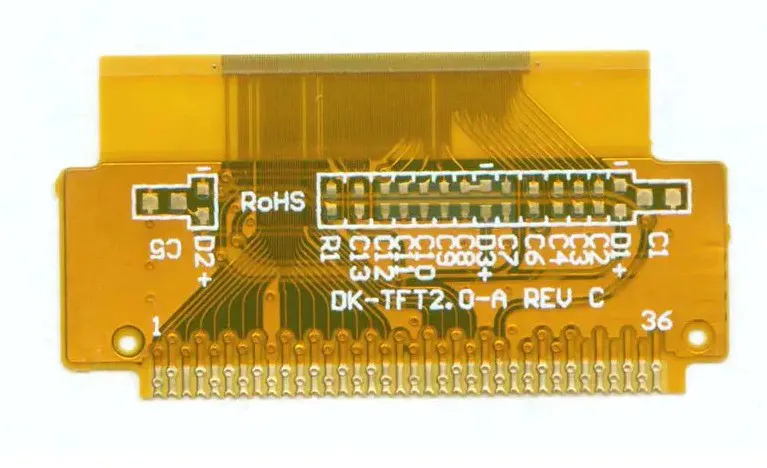
After testing the prototype, I finally designed my PCB.
I am very satisfied with the results.
In this tutorial I will teach you how to make your own PCB from a prototype.
I took my 555 doorbell circuit as an example to demonstrate the whole process.
In the final step, I have attached the PCB File for this small item.
You can download.
So let\'s get started, don\'t spend too much time! [Play Video ]Parts :1. 555 Timer (NE555N ): Amazon2.
Electrolytic capacitors (
1x10 uF and 1x100 uF): Amazon 3.
Ceramic Capacitors (3 x 10nF ): Amazon 4. Diode (2 x IN4148 ): Amazon5. Resistor (4 x 47K ): Amazon6. Speaker (8 Ohm ): Amazon7.
9v battery: amazon8.
Button: amazon9.
Battery clip: Amazon tools: 1.
Soldering iron: amazon2.
A: Amazon3.
Welding pump: The Amazon doorbell circuit is a pause mode based on the 555 timer (
No stable state).
Timer in 555 Astable mode: connection diagram of astable multi-vibrator 555 timer as shown in the above figure (fig -3 ).
Pin 1 ground;
Pins 4 and 8 short circuit, then connect to the power supply Vcc, output (
VOUT from pin 3;
Pins 2 and 6 short circuit, connected to ground via capacitor C1, pin 7 connected to power supply VCC via resistor R1;
A resistor R2 is connected between pins 6 and 7, and pin 5 is grounded by the capacitor c2.
Description: In the figure of 555 (fig -1 )
There are two comparators, one on the pin-2 (Inverting )
And others in pin-6 (Non Inverting ).
Input voltage at the pin-
2 is less than 1/3 of Vcc, and the output is higher.
But when this output is connected to the setup terminal of the trigger, the output (Q )
High output and complementary (Q comp)goes LOW.
It is connected to the bottom of the discharge transistor, so the transistor will be turned off.
Input voltage at the pin-
6 2/3rd greater than Vcc, compare the output high level and reset the trigger, output (Q )
Low, high complementary output.
The discharge transistor will be turned on.
External components (fig-3 )
Capacitance (C1 )
Will be charged via R1 and r2.
When the voltage of pin 6 reaches 2/3Vcc, the capacitor voltage rises (2/3 x 9V = 6V )
, Discharge transistor open, capacitor (C1)
Start discharging through r2.
In the process of discharge, when the capacitor voltage is less than 1/3rd Vcc, the capacitor voltage will gradually decrease (9x 1/3 =3 V ), the output (Q )
High level, the discharge transistor is turned off.
Therefore, the charging process starts again and the capacitor voltage rises, which is repeated repeatedly in a circular manner.
Conclusion: the output signal is composed of high level and low level.
If you connect an LED to this circuit, it will flash.
However, if you connect the Speaker, it produces sound based on the frequency of the output wave.
Doorbell circuit: Schematic diagram of doorbell (fig -4 ), when switch (S1)
After pressing, both diodes will be turned on. So pin -
4 Promotion to Vcc (
Ignore diode voltage drop).
In the square picture, you can see that a non-door is attached to the pin. 4.
So the 555 timer will reset.
During this period, there are only two resistors in the capacitor (C4)circuit. (
Bypass resistor R1).
So when you press the switch, the charging time constant is (R2 + R4 )
X C4, when the switch is released, the charging time constant is changed (R1 + R2+ R4 )x C4.
To make a professional PCB, a prototype is first made.
However, when you make a design prototype, it is a very good practice to test your design before you start making a pcb.
Whenever you find that there is a problem with your design and have to make a new batch of pcb, you will increase the cost in time and money.
Before making a PCB, it is best to design as perfectly as possible. Prototyping :1.
Breadboard: First of all, we will make the circuit on the breadboard.
The main advantage of the welded bread plate is that there is no welding.
Therefore, you can easily change the design by simply unplugging the components and leads as needed. 2.
Perforated plate: After doing the bread plate test, I made the circuit on the perforated plate.
Make it follow the instructions below I)
First insert all the parts into the holes of the perforated Boardii)
Weld all assembly pads and trim the extra legs by means of pliers. iii)
According to the schematic diagram, use the wire to connect the pads. iv)
Use an isolation device to isolate the circuit from the ground.
The perforated plate circuit is very powerful and can be permanently deployed in the project.
After testing the prototype, we can start designing the final PCB if all goes well.
The Autodesk circuit has a huge function of \"bread plate prototyping.
You can make the same circuit and then simulate without using physical components.
You don\'t have to install the software either.
This is a web-based platform.
So in the next step, we will learn it.
To get started, click here and register.
To make a breadboard circuit on an Autodesk circuit, follow these steps.
Open Electronic Laboratory
New electronic label
The default breadboard will appear automatically.
But you can select the desired breadboard by clicking on the \"components\" and then searching for the breadboard. 3.
Populate the component by searching in the components list. 4.
For multiple numbers of the same component, use copy (Ctl +C )and paste (Ctl +V ). 5.
To change the value of the component, click the component and change it in the dialog box. 6.
Arrange the components on the breadboard. 7.
Make circuits using color wires.
To change the wire color, click the wire and change it in the dialog box. 8.
You can bend the wire when needed by clicking the left mouse button.
For more details, you can simulate the circuit by clicking \"start simulation.
Note: to rotate the component, use \"R\" on the keyboard \".
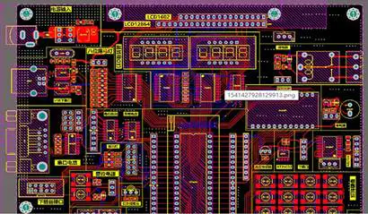
To draw a schematic, click \"PCB design\" on the left \"-
Then open a new page.
Click on the new \"New PCB Design \". 3.
To add a component, click components in the upper right corner \".
Then search for the desired component and click add 4.
Follow the same steps to add all components. 5.
Copy is used by the replication component (Ctl +C )and paste (Ctl +V ). 6.
To change the value of the component, click the component and change it in the dialog box. 7.
Schedule components. 8.
All components are added to the schematic, and now is the time to connect them together. 9.
By default, the schematic is an unnamed file.
So it\'s a good practice to name this file and save it. (
Top left corner)
Note: to rotate the component, use \"R\" on the keyboard \". 1.
After completing the schematic, switch to the PCB view.
This icon is located in the upper right corner. 2.
All the components added in the schematic should be there, stacked together, ready to be placed and routed. 3.
The green gold wire known as airwires is connected between pins and reflects the network connection you have established on the schematic. 4.
Drag the component by grabbing the pad of the component.
Then place it inside the rectangular border line. 5.
Arrange all components in a way that the board takes up minimal space.
The smaller the board size, the lower the
PCB manufacturing cost. 6.
It would be useful if the board had some mounting holes so that it could be installed in the enclosure.
Before we start wiring Air Lines, now is a good time to add holes. 7.
After arranging the assembly and drilling holes, drag the border line. 8.
Now you have to walk.
Routing is the most interesting part of the process.
It\'s like solving a problem!
Your job will be to turn these green wires to the top (red )or bottom (blue )copper traces.
At the same time, you also have to make sure you don\'t overlap two different tracks. 9.
Click \"copper trace\" and select the track size (
Power cord or signal line).
Now complete the track according to the green wire path. 10.
Whenever you face the overlap of the track, switch to the ground floor and follow the same procedure. 11.
If there is an error, a yellow dot with the error message appears.
Correct the error. 12.
You can add tags on any layer by clicking on \"tags.
You can watch this video while making the PCB.
Copper pouring is usually a good complement plate.
They look professional.
Usually, it\'s for ground signals when you add copper. 1.
Click copper pour in the menu bar in the upper left corner \". 2.
Click on any ground terminal of the component to create a border line (dotted line )
Right outside the main border.
Once the path is off, it will automatically pour the copper into the entire board. 3.
Switch to the bottom and follow the same program.
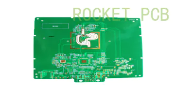
After making the PCB, we have to generate files that can be sent to the PCB manufacturing company which will send us some real PCB in due course.
In Autodesk circuits, it is very easy to generate a Gerber file from a PCB.
Just go to the overview page and click \"Download Gerber \".
The zip folder will be downloaded.
The Zip folder contains 8 files 1.
Copper at the bottom :. gbl2. Top Copper: . gtl3.
Welding mask at the bottom :. gbs4.
Top welding mask :. gts5.
Bottom screen :. gbo6.
Top Screen :. gto7. Drill: . drl8. Outline: .
Outline you can download my 555 doorbell gerber file.
It\'s time to find a
PCB manufacturer that can turn our gerber files into real ones.
For manufacturers like our OSH Park, Seeed Studio and dirty PCB provide very good service.
I always prefer OSH park for the small quality of the PCB.
3 numbers in one square inch, they charge $5.
Follow the steps: 1.
Go to the website of Oz Park 2.
Click start now \". 3.
Click Select file on your computer \".
Select the downloaded gerber file (. zip )
The previous steps. 4.
Now you can give the name and some description of the project.
Then click continue \".
A new page will open where you can find pictures related to all the gerber files discussed earlier. 5.
If everything looks good, you can place an order by clicking \"approve and order.
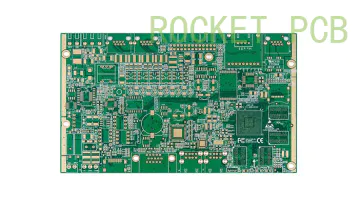
After receiving the board from PCB fab house, you have to weld the assembly.
For welding, you need a decent soldering iron, soldering tin, pliers, deswelded Wick or pump and 10 thousand kWh.
It is good practice to weld parts according to the height of the components.
First weld the components at a smaller height.
You can weld the assembly as follows: 1.
Cross the component legs through their holes and turn the PCB back. 2.
Keep the tip of the soldering iron at the junction of the pad and the part leg. 3.
Feed the solder into the joint so that it flows around the lead and covers the pad.
Once it flows around, remove the tip.
Congrats! ! ! .
Now your board is ready.
Hope you like it and can make your own PCB.
I am eagerly waiting for your first PCB picture in the review.
Thank you for reading this instruction.
If you like, don\'t forget to share it.