


Teach you how to make simple PCB at home- heat transfer printing
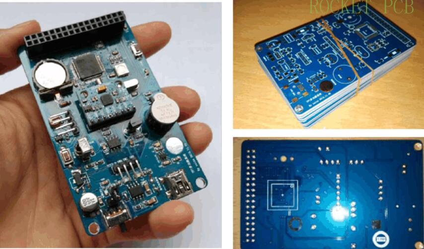
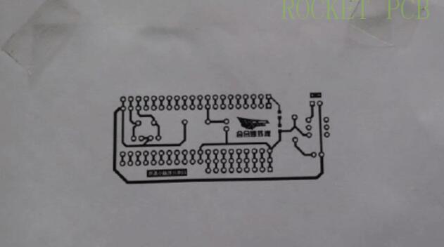
PCB means printed circuit board. It draws and "prints" all the circuits we need on the board. It looks like this.
Before we learn how to make PCB, if we want to solder a circuit, I believe we all choose to use "hole board" to do it. Like this.
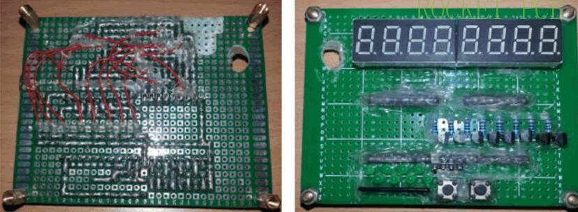
Compared with the previous one, it is not difficult to find that the former is more beautiful and more convenient. You just need to solder the corresponding components in the right place, there is no need to consider what kind of circuit, and the latter is more convenient, faster and cheaper when making some simple circuits. Therefore, when your circuit has chip components, complex circuit, small size, beautiful circuit, good stability, you should choose to do PCB board.
What does the PCB we want to make look like?
Of course, the PCB board shown in Figure 1 is considered to be a real PCB board. If it is so well done, it can only be processed by the PCB factory. The PCB that we want to make by ourselves is actually a different look.
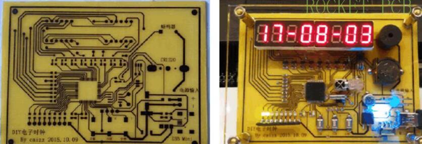
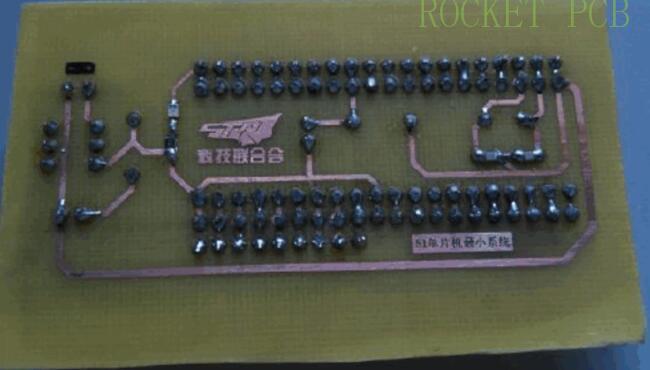
For example, this circuit is the same as the previous clock circuit of the hole board. It can be seen that the clock that used to be made of two layers of hole boards can now be compressed to one layer of the board. There are also very few jumpers, and the appearance also looks much more advanced. This is the actual effect picture of our self-made PCB. Compared with the PCB board made by the factory, it lacks the green oil of the solder mask layer, the text label of the silk screen layer and a layer of wiring (our self-made PCB generally only makes one layer), but it is also sufficient , and the cost is very cheap.
Hardware materials:
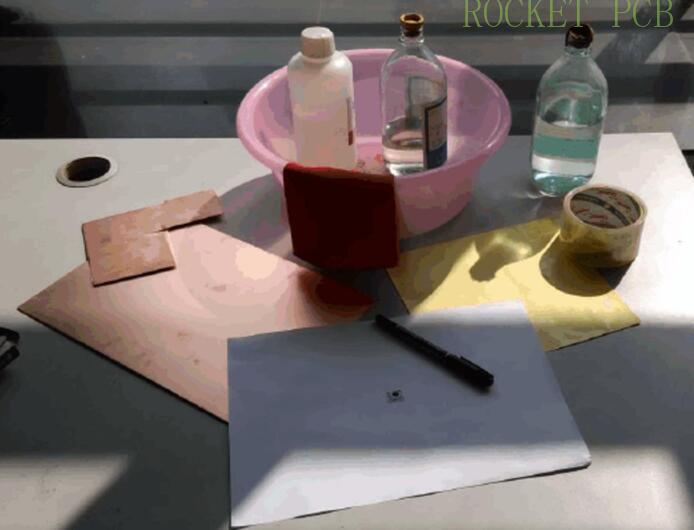
Basic tools such as copper clad laminate, A4 paper, thermal transfer paper (yellow one), scotch tape, marker pen, hydrochloric acid, hydrogen peroxide (30%), basin, gloves, shears, sandpaper, etc.
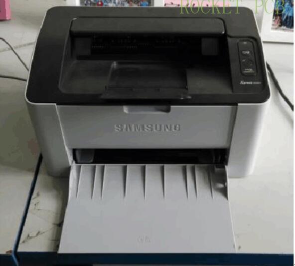
Laser printer
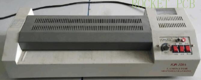
Laminator
Software materials:
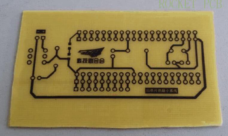
PCB diagram (taking 51 minimum system as an example)
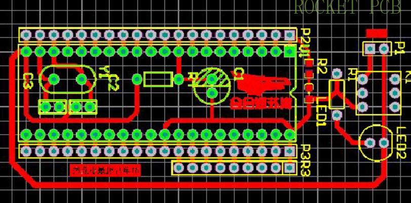
Print out is a PDF document, open the document to get the circuit diagram we want
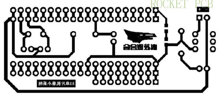
Print to A4 paper for positioning
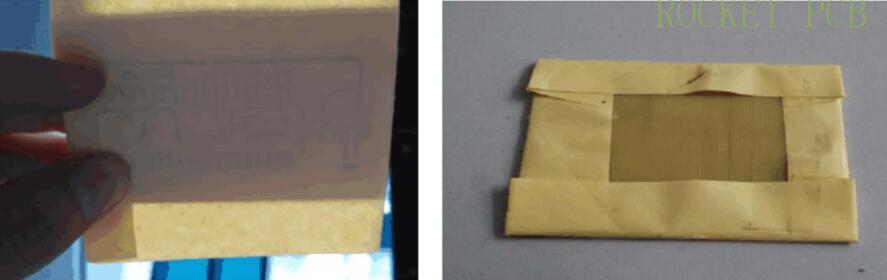
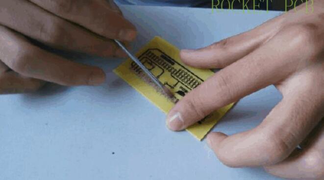
Print on heat transfer paper
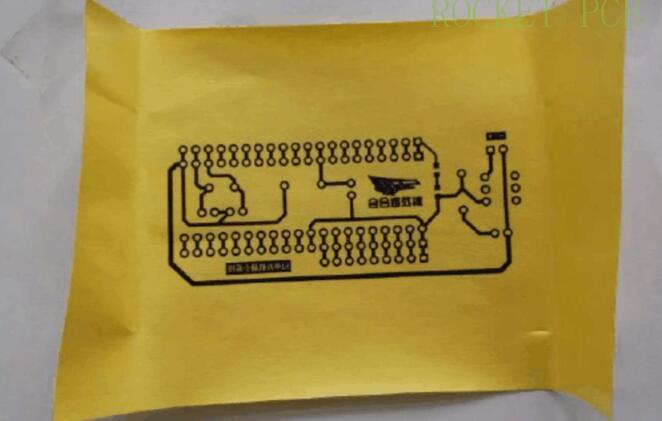
Smooth side up, and then put it into the printer to type again, the circuit is printed on the smooth surface of the transfer paper.
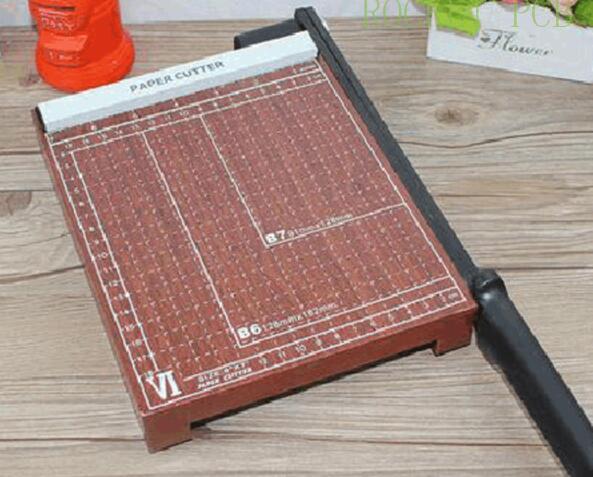
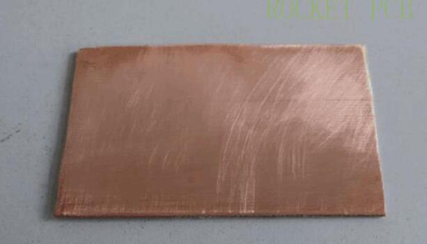
Use a paper cutter or scissors to cut out the copper clad laminate which is larger than the circuit, and properly grind it with sandpaper to remove the oxide layer.
Paper cutter
Sandpaper
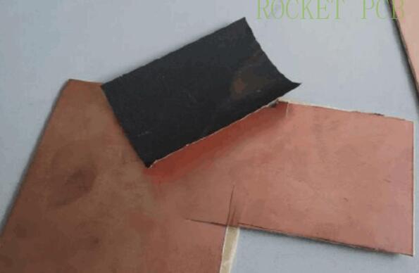
Prepared CCL
Heat transfer to copper plate
Keep your back to the sun and cover the board with tape
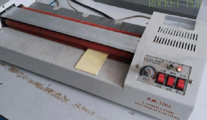
Adjust the superplasticizer to the maximum temperature of 200 ℃, put the wrapped board in and roll back for at least 10 minutes. In principle, the bigger the board, the longer it takes to roll, and the longer the time, the higher the success rate.
Check whether the transfer is successful
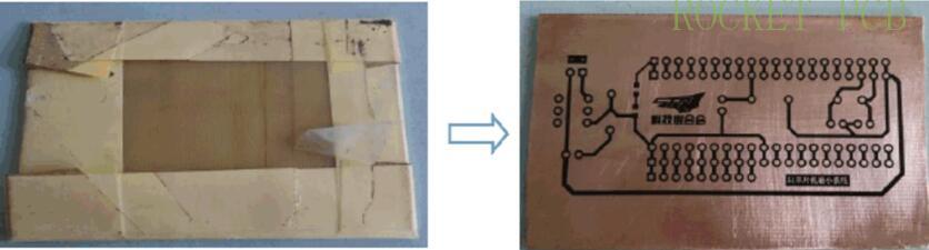
After the molding is finished, the exciting moment is to unpack and check whether the transfer is successful. In fact, due to various reasons, it is not guaranteed that every time the transfer is completed, If a small part is not printed (for example, a small section of circuit has not been printed), repair it with a marker pen, However, if there are too many missing parts, remove the carbon powder on the surface and start the transfer again. After successful transfer, we can see the very beautiful circuit pattern on the copper plate!
Preparation of etching solution
Hydrochloric acid and hydrogen peroxide are mixed into a strong acid corrosion solution by about 3:1, and then diluted with 1 part of water. There are two effects of adding water here. One is to reduce hydrochloric acid and hydrogen peroxide solution
The second is to reduce the corrosion rate and make it more controllable
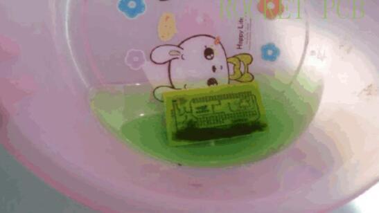
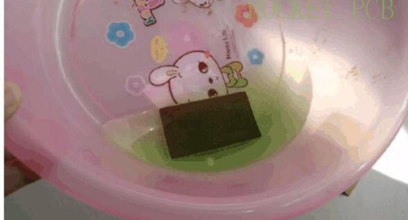
It starts to bubble as soon as it's put in
Ripple back and forth, accelerate the corrosion rate
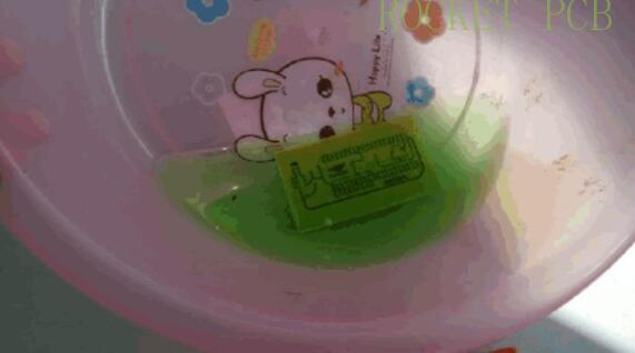
Finally, the bare copper disappears, revealing the color of the substrate
Take it to flush (don't take it directly with your hands), dry it, and you can see the beautiful board!
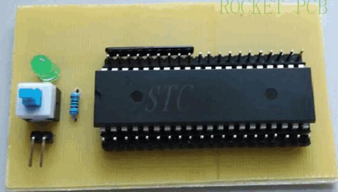
This is our home-made PCB board
Drilling, soldering
Remove the carbon powder from the pad and retain the carbon powder in the circuit part
This is a PCB made by heat transfer printing. In addition, there is another method called photosensitive method, but it needs special photosensitive plate or film, and UV lamp box and film remover. Generally, the thermal transfer method is commonly used, and I will explain it in detail in the next article. If you are interested, you can learn about.


