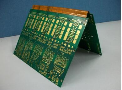
Rigid-flex PCB Application
The application scope of rigid-flex PCB mainly includes aerospace, such as high-end aircraft-mounted weapon navigation system, advanced medical equipment, digital camera, portable camera, and high-quality MP3 player. Rigid-flex PCBs are most commonly used in military aircraft and medical equipment. A rigid-flex composite board has brought great benefits to the design of military aircraft because it can improve the reliability of the connection and reduce the weight. Of course, the benefits from a smaller overall volume can not be ignored.
Although the cost of a rigid-flex composite board is higher than that of a traditional rigid PCB board, it provides an ideal solution for the project. The use of flexible substrate interconnections, rather than multiple PCB connection equipments, is the key to reducing footprint and weight, which is required by many designs.
Characteristics of rigid-flex PCB
Rigid-flex board has the characteristics of both rigid PCB and flexible PCB. It can bend, fold and shrink with the following characteristics:
1) Flexible and three-dimensional installation, effective use of installation space, reduce the volume of finished products.
2) It has the strength of a rigid plate and plays a supporting role.
3) Rigid-Flex PCB has a small volume and is lightweight, which makes the product light and thin.
4) Rigid-Flex PCB has higher assembly reliability.
5) It has excellent electrical properties, dielectric properties, and heat resistance.
6) It is difficult to make, high one-time cost, and can not be repaired after damage.
Introduction of rigid Flex PCB material
Rigid-flex PCB is a product composed of the rigid circuit board (FR4) and flexible circuit board (FCCL) through adhesive.
The flexible board is thin and flexible. It is generally divided into glue base material and nonglue base material.
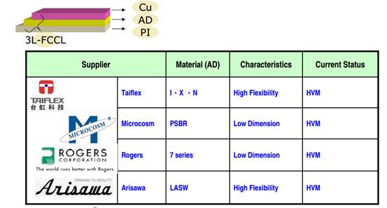
Glued material: copper foil + adhesive layer + substrate
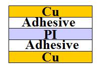
It has the advantages of low price, good dimensional stability, good adhesion between the copper sheet and medium. Due to a variety of resin compositions, heat resistance is general, easy to delamination
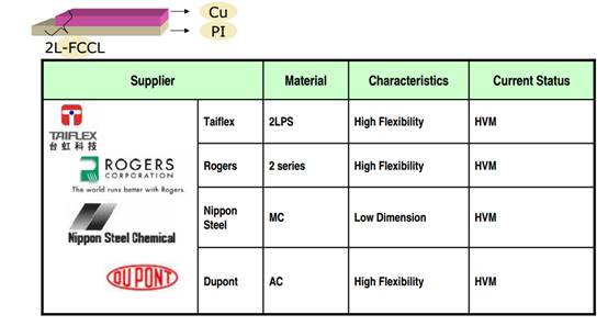
Glueless material: copper foil + base material
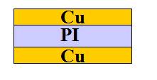
High price, single resin, good thermal stability, high reliability, but copper skin adhesion is slightly poor
Copper foil of the rigid-flex board
It can be divided into rolled annealed copper foil (RA) and electrolytic copper foil (ED). The bending property of rolled copper foil is better than that of electrolytic copper foil, and the products with deep and high requirements for flexure are mainly used. Electrolytic copper foil is conducive to fine circuit production and is used for products with low requirements for flexibility.

Conductive Layer:
RA copper: Rolled Annealed Copper (9pum12um/17.5um35um70pum). High flex life, good forming characteristics. The crystal structure of calendered copper is smooth, but its adhesion to the substrate is poor.
ED copper: Electrodeposited Copper(17.5um/35um/70um). More cost-effective. The rough crystal structure of electrolytic copper is not conducive to the yield of a fine circuit.
Silver Ink: Most cost-effective, poor electrical characteristics. Most often used as shielding or to make connections between copper layers.
The recommended use case of RA and ED copper
Application | Recommended use |
Flexible board of dynamic continuous action | RA |
Flexible board with little continuous action for very fine lines | ED |
A flex board that is not dynamic but must bear motion | RA |
Flexible board with double electroplated through holes | RA&ED |
Products with large radius and low deflection | ED |
Nondynamic flex board | ED |
>Bending assembly of 100m bending radius | ED |
The substrate material of Rigid-flex PCB
Divided into polyimide (PI), polyester (PET), polytetrafluoroethylene (PTFE)
Polyimide (PI): Kapton TM (125um/ 20um/ 25um/ 50 μm/ 75um)
It has excellent high-temperature resistance, immersion welding resistance up to 260 ℃, 20sec, high dielectric strength, good electrical and mechanical strength, but easy to absorb moisture. It is a common base material for FPC
Polyester (PET): (25um / 50 μ M / 75um)
Many properties are similar to polyimide, but poor heat resistance can only be used at room temperature.
Polytetrafluoroethylene (PTFE): only used in high-frequency products with low dielectric constant
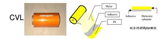
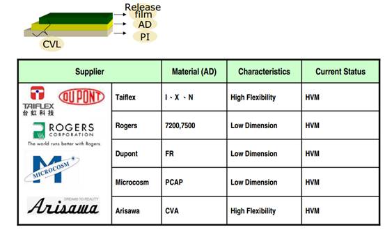
Coverlay: Cover layer from 2 mils to 5 mils (12. 7 to 127um)
The covering film is equivalent to the solder resist ink of rigid circuit board, which plays a role in solder resistance. The covering film is composed of adhesive +PI.
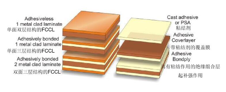
FCCL, CVL, and Adhesive


FPC material- 2-layer FCCL Status
FPC material-3-layer FCCL Status
FPC material- coverlay layer Status
Coverlay used for rigid-flex board
Comparison of coverlay features

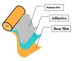
Structure of the FCCL
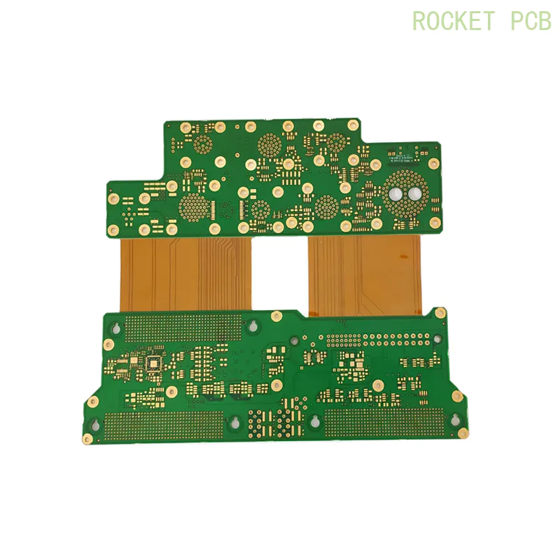
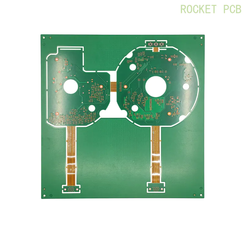
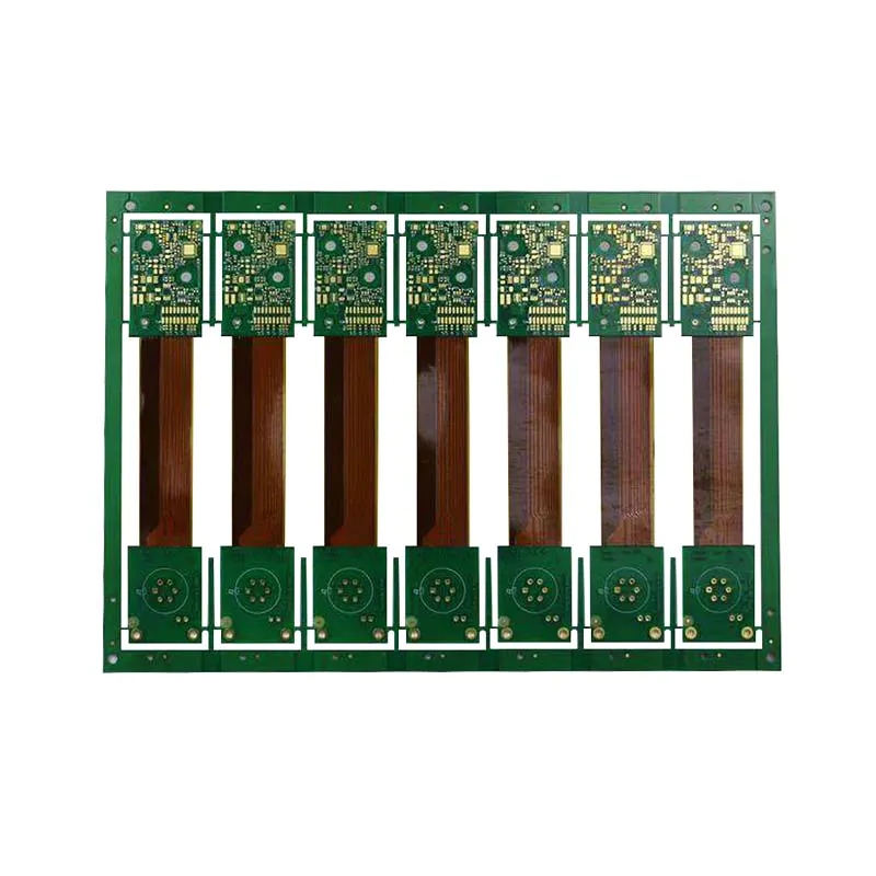
Rigid-flex Sample Projects

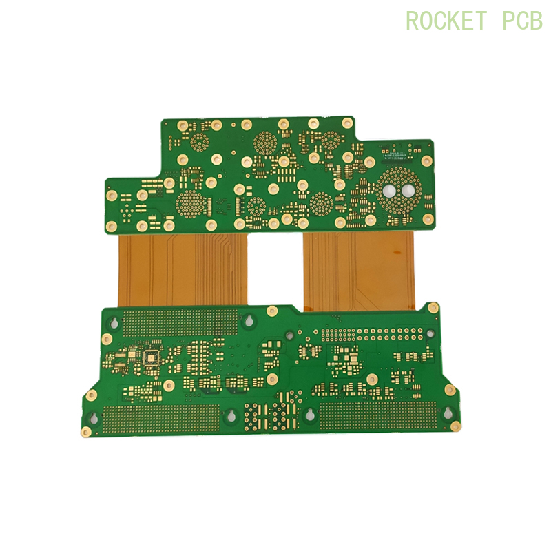
There are many differences between rigid PCB and flexible PCB board in circuit design
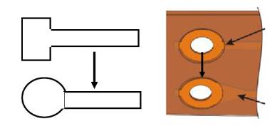
Line design requirements inflexible area
To avoid sudden expansion or reduction of the line, use tear shape between thick and thin lines
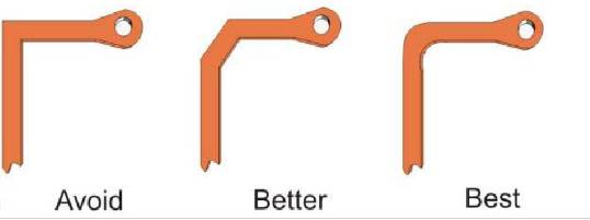
It is recommended to use the smooth angle to avoid acute angle
Design key considerations
The structure is the most important factor in the design of rigid-flex. It is necessary to make the process simple and reliable and achieve the goal of low cost and applicability
1. The thickness should be as low as possible and the material types must be reduced. Too thick rigid-flex not only has an adverse effect on the miniaturization of thick assembly products but also causes inconvenience to the manufacturing process (especially the press-fit). In addition, rigid-flex materials include copper foil, polyimide film, and acrylic glue. Because of the difference in thermal expansion coefficient, attention should be paid to the adhesion between layers after thermal shock.
2. Stress prevention of bending point. In addition to reducing the stress of the contact edge between the flexible board and the rigid board or reinforcing it in the process of hot pressing, it is better to avoid the bending point.
3. Considering the mainshock resistance, the wiring arrangement should meet the requirements of folding resistance. If the product is applied in a high vibration environment, it is also necessary to investigate in advance.
4. In the aspect of the manufacturing process, the possible problems in the process are foreseen, and the process is simplified to reduce the cost and improve the yield.


 China Rigid Flexible Rigid-flex Printed Circuit Boards PCB ManufacturerInquire
 Custom Rigid-flex Printed Circuit Boards FPC PCB Manufacturer✓ 24-hour real-time technical support ✓ Quick turn around with 24 hours and instant quote ✓ Effective and flexible PCB engineering solutions save your cost ✓ State-of-the-art PCB including rigid, FPC, rigid-flex, metal base, RF/microwave, hybrid, HDI, embedded, LED, backplane, a ceramic substrate, IC substrate ✓ Strong partnerships with different reputed material suppliers such as Rogers, Arlon, Nelco, and Taconic can realize a fast service to a wide range of PCB applications ✓ Superb quality is guaranteed under the ISO9001, ISO14001, TS16949, OHSAS18001, ISO/IEC27001 system, insist on adopting 5S methods, Lean Six Sigma quality systems ✓ Complete service from free DFM, traceable manufacturing to complete after-sales service ✓ On-time delivery more than 99%Inquire
 Custom Rigid-flex Printed Circuit Boards PCB Manufacturer multilayer rigid-flexInquire


