


High-speed PCB design basics Q&A
1. About high-speed design and wiring
Q: What are the layout ideas
A:Rule-driven design, advance planning, and block diagram drawing
Prioritized processing of key signals
Whole board wiring
Power and ground processing
Equal length winding
Wiring optimization
2. In high-speed design, how to solve the signal integrity problem? How to implement differential wiring? For clock signal lines with only one output end, how to implement differential wiring?
A: Signal integrity is basically an impedance matching problem. The factors that affect impedance matching include the architecture and output impedance of the signal source, the characteristic impedance of the routing, the characteristics of the load end, and the topology of the routing. The solution is to rely on termination and adjust the topology of the routing. There are two points to note when routing differential pairs. One is that the lengths of the two lines should be as equal as possible, and the other is that the spacing between the two lines (this spacing is determined by the differential impedance) should always remain unchanged, that is, they should remain parallel. There are two ways to be parallel, one is that the two lines are routed on the same routing layer (side-by-side), and the other is that the two lines are routed on the upper and lower adjacent layers (over-under). Generally, the former side-by-side is more often implemented. To use differential wiring, it must be that the signal source and the receiving end are also differential signals. Therefore, differential wiring cannot be used for clock signals with only one output end.
Experts A questions about high-speed line wiring 2
3. About high-speed differential signal wiring
Q: When high-speed differential signal lines are parallel and close to each other on a PCB, there will be many benefits due to the mutual coupling of the two lines under the condition of impedance matching. However, some people believe that this will increase signal attenuation and affect the transmission distance. Is this true? Why? I have seen high-speed wiring on the evaluation boards of some large companies. Some are as close and parallel as possible, while others intentionally make the distance between the two lines different. I don’t know which one is better. My signal is above 1GHz and the impedance is 50 ohms. When using software to calculate, is the differential line pair also calculated as 50 ohms? Or is it calculated as 100 ohms? Can a matching resistor be added between the differential line pairs at the receiving end?
A: The reason for the attenuation of high-frequency signal energy is the resistance characteristics of the conductor itself (conductor loss), including the skin effect (skin effect), and the dielectric loss of the dielectric material. When analyzing the transmission line effect (transmission line effect) in electromagnetic theory, the degree of their influence on signal attenuation can be seen. The coupling of differential lines will affect the characteristic impedance of each line, making it smaller. According to the voltage divider principle, this will make the voltage sent by the signal source to the line smaller. As for the theoretical analysis of signal attenuation due to coupling, I have not seen it, so I cannot comment. The wiring method of the differential pair should be appropriately close and parallel. The so-called appropriate closeness is because this spacing will affect the value of differential impedance, which is an important parameter for designing differential pairs. Parallelism is also required to maintain the consistency of differential impedance. If the two lines are far or near, the differential impedance will be inconsistent, which will affect signal integrity and timing delay. The calculation of differential impedance is 2(Z11 - Z12), where Z11 is the characteristic impedance of the line itself, and Z12 is the impedance generated by coupling between the two differential lines, which is related to the line distance. Therefore, when designing a differential impedance of 100 ohms, the characteristic impedance of the line itself must be slightly greater than 50 ohms. As for how much greater it should be, it can be calculated using simulation software.
4. Q:To improve the anti-interference performance, in addition to separating the analog ground and digital ground and connecting them only at the power supply point, thickening the ground wire and power supply line, I hope the experts can give some good opinions and suggestions!
A: In addition to separating and isolating the ground, you should also pay attention to the power supply of the analog circuit part. If you share the power supply with the digital circuit, it is best to add a filter line. In addition, digital signals and analog signals should not be intertwined, especially not crossing the place where the ground is divided (moat).
5. About the copper grounding problem of the blank area of the signal layer in high-speed PCB design
Q: In high-speed PCB design, the blank area of the signal layer can be copper-plated. So is it better to ground the copper of multiple signal layers, or half of it to the ground and half to the power supply?
A: Generally, the copper in the blank area is grounded in most cases. Just pay attention to the distance between the copper and the signal line when copper is applied next to the high-speed signal line, because the copper applied will reduce the characteristic impedance of the trace a little. Also be careful not to affect the characteristic impedance of other layers, such as in the dual stripline structure.
6. High-speed signal line matching problem
Q: In the layout of high-speed boards (such as P4 motherboards), why do high-speed signal lines (such as CPU data and address signal lines) need to be matched? What hidden dangers will arise if they are not matched? What factors determine the length range of the matching (i.e. the time delay difference of the signal line) and how to calculate it?
A: The main reason for requiring matching of the characteristic impedance of the routing is to avoid the reflection caused by the high-speed transmission line effect affecting the signal integrity and flight time. In other words, if there is a mismatch, the signal will be reflected and its quality will be affected. The length range of all routing lines is determined according to the timing requirements. There are many factors that affect the signal delay time, and the routing length is only one of them. P4 requires that the length of certain signal lines must be within a certain range, which is based on the timing margin calculated under the transmission mode used by the signal (common clock or source synchronous), and a part of the allowable error of the routing length is allocated. As for the calculation of the timing of the above two modes, it is not convenient to explain it in detail here due to time and space limitations. Please download the "Intel Pentium 4 Processor in the 423-pin Package/Intel 850 Chipset Platform Design Guide" from the following website: http://developer.intel.com/design/Pentium4/guides. The "Methodology for Determining Topology and Routing Guideline" section has a detailed description.
7. Q: Can the test points automatically generated by software on high-density printed circuit boards generally meet the test requirements of mass production? Will adding test points affect the quality of high-speed signals?
A: Generally, whether the test points automatically generated by software meet the test requirements depends on whether the specifications for adding test points meet the requirements of the test equipment. In addition, if the routing is too dense and the specifications for adding test points are strict, it may not be possible to automatically add test points to each line. Of course, you need to manually fill in the places to be tested. As for whether it will affect the signal quality, it depends on the way of adding test points and how fast the signal is. Basically, the additional test points (without using the existing through holes (via or DIP pin) on the line as test points) may be added to the line or a small line may be pulled out from the line. The former is equivalent to adding a very small capacitor on the line, and the latter is an additional branch. Both of these situations will have a little impact on the high-speed signal, and the extent of the impact is related to the frequency speed of the signal and the edge rate of the signal. The size of the impact can be known through simulation. In principle, the smaller the test point, the better (of course, it must meet the requirements of the test equipment) and the shorter the branch, the better.
8. How to choose PCB material? How to avoid high-frequency interference of high-speed data transmission on surrounding analog small signals? Are there some basic design ideas? Thank you
A: The selection of PCB material must strike a balance between meeting design requirements, mass production and cost. Design requirements include electrical and mechanical parts. Usually, this material issue is more important when designing very high-speed PCB boards (frequencies greater than GHz). For example, the dielectric loss of the commonly used FR-4 material at a frequency of several GHz will have a great impact on signal attenuation, and it may not be suitable. In terms of electrical, it is necessary to pay attention to whether the dielectric constant and dielectric loss are suitable for the designed frequency. The basic idea of avoiding high-frequency interference is to minimize the interference of the electromagnetic field of high-frequency signals, which is the so-called crosstalk. You can increase the distance between high-speed signals and analog signals, or add ground guard/shunt traces next to analog signals. Also pay attention to the noise interference of digital ground to analog ground.
9. As we all know, PCB boards include many layers, but I am not very clear about the meaning of some of them. I don't know the exact meaning of mechanical, keepoutlayer,topoverlay,bottomoverlay,toppaste,bottompaste,topsolder,bottomsolder,drillguide, drilldrawing, multilayer. I hope you can teach me.
A: In the specialized terms of EDA software, many of them are not defined in the same way. The following is an explanation of the possible meanings of the literal meaning.
Mechanical: Generally refers to the dimensioning layer of board-type mechanical processing
Keepoutlayer: Defines the area where wiring, vias, or parts cannot be routed. These restrictions can be defined separately. Topoverlay: Its meaning cannot be known from the literal meaning. Provide more information for further discussion.
Bottomoverlay: Its meaning cannot be known from the literal meaning. Provide more information for further discussion.
Toppaste: The part of the solder paste on the copper foil that needs to be exposed on the top layer.
Bottompaste: The part of the solder paste on the copper foil that needs to be exposed on the bottom layer.
Topsolder: should refer to the top solder mask layer, to avoid accidental short circuits during the manufacturing process or future maintenance. Bottomsolder: should refer to the bottom solder mask layer.
Drillguide: may be a table of different hole sizes, corresponding symbols, and numbers.
Drilldrawing: refers to the hole location map, each different hole size will have a corresponding symbol.
Multilayer: there should not be a separate layer, which can refer to multilayer boards, for single-sided and double-sided boards.
10. A system is often divided into several PCBs, including power supply, interface, motherboard, etc. The ground wires between each board are often interconnected, resulting in the formation of many loops, such as low-frequency loop noise. I wonder how to solve this problem?
A: When the signals or power supplies between the interconnected PCB boards are in action, for example, when the power supply or signal of board A is sent to board B, there must be an equal amount of current flowing back from the ground layer to board A (this is Kirchoff current law). The current on the ground layer will flow back to the place with the smallest impedance. Therefore, at each interface where power or signals are connected to each other, the number of pins allocated to the ground layer cannot be too small to reduce impedance, which can reduce noise on the ground layer. In addition, the entire current loop can be analyzed, especially the part with larger current, and the connection method of the ground layer or ground wire can be adjusted to control the flow of current (for example, create low impedance at a certain place to let most of the current flow from this place) to reduce the impact on other more sensitive signals.
11. (1) Can you provide some empirical data, formulas and methods to estimate the impedance of the wiring? (2) When the impedance matching requirements cannot be met, is it better to add a parallel matching resistor at the end of the signal line or a series matching resistor on the signal line? (3) Can a ground line be added in the middle of a differential signal line?
A: 1. The following are two commonly referenced characteristic impedance formulas: a. Microstrip Z={87/[sqrt(Er+1.41)]}ln[5.98H/(0.8W+T)] Where W is the line width, T is the copper thickness of the trace, H is the distance from the trace to the reference plane, and Er is the dielectric constant of the PCB material. This formula can only be applied when 0.1<(W/H)<2.0 and 1<(Er)<15. b. Stripline Z=[60/sqrt(Er)]ln{4H/[0.67π(T+0.8W)]} Where H is the distance between the two reference planes, and the trace is located in the middle of the two reference planes. This formula can only be applied when W/H<0.35 and T/H<0.25. It is better to use simulation software to calculate more accurately.
2. There are several factors to consider when choosing the termination method: a. The structure and strength of the signal source (source driver). b. The size of power consumption. c. The impact on time delay, which is the most important consideration. Therefore, it is difficult to say which termination method is better.
3. Generally, a ground wire cannot be added in the middle of the differential signal. Because the most important point of the application principle of differential signals is to use the benefits brought by the mutual coupling (coupling) between differential signals, such as flux cancellation, noise immunity, etc. If a ground wire is added in the middle, the coupling effect will be destroyed.
12.Design and processing of flexible circuit boards
Our company intends to use flexible circuit board design to solve the problem of signal transmission and circuit board interconnection in small imaging systems. Does the design of rigid-flexible boards require special design software and specifications?
A: You can use general PCB design software to design flexible printed circuits (Flexible Printed Circuit). The Gerber format is also used for FPC manufacturers to produce. Since the manufacturing process is different from that of general PCBs, each manufacturer will have restrictions on the minimum line width, minimum line spacing, and minimum aperture (via) based on their manufacturing capabilities. In addition, some copper foil can be laid at the turning point of the flexible circuit board for reinforcement.
13. PCB wiring adjustment
I would like to ask a question: I feel that the machine wiring is not satisfactory, and it takes time to adjust it. I usually use manual wiring. Most of the PCB boards now use chip packaging chips with high pin density and buses (ABUS, DBUS, CBUS, etc.). Because the working frequency is high, the leads should be as short as possible. Naturally, very dense signal lines are evenly distributed on a small area of the board. I now feel that it takes more time to adjust these dense signal lines. First, adjust the distance between the lines to make it as uniform as possible. Because in the process of wiring, generally, the lines need to be changed from time to time. Every time you change it, you have to re-even the spacing of each already laid line. The closer you are to the end of the wiring, the more this situation occurs. The second is to adjust the width of the line so that it can accommodate the newly added lines as much as possible within a certain width. Generally, there are many bends on a line, and each bend is a section. Manual adjustment can only be made section by section, which is also time-consuming. I think if I can roughly draw the wires manually according to my ideas during the wiring process, the software can help me adjust them automatically from these two aspects after I finish. Or even if I have finished the wiring, if I need to change the wires, I will just roughly change them and then let the software adjust them. Even in the end, I feel that I need to adjust the package of the components, that is, the entire wiring needs to be adjusted, and I let the software do it. That will be much faster. I use Protel98. I know that this software can automatically and evenly adjust the distance of the component packages but cannot automatically adjust the line spacing and line width. Maybe I don’t know how to use some of its functions yet, or there are other ways. I would like to ask for advice here.
A: Line width and line spacing are two important factors that affect the routing density. Generally, when designing a board with a higher operating frequency, the characteristic impedance of the routing needs to be determined before routing. When the PCB stacking is fixed, the characteristic impedance will determine the appropriate line width. The line spacing has an absolute relationship with the size of crosstalk. The minimum acceptable line spacing depends on whether the impact of crosstalk on signal time delay and signal integrity is acceptable. This minimum line spacing can be obtained by pre-simulation of simulation software. In other words, before routing, the required line width and minimum line spacing should have been determined and cannot be changed at will, because it will affect the characteristic impedance and crosstalk. This is why most EDA routing software will not change the line width and minimum line spacing when doing automatic routing or adjustment. If the line width and minimum line spacing have been set in the routing software, the convenience of routing adjustment depends on the strength of the software winding engine.
14. About high-speed digital PCB
What are the principles for properly selecting the grounding point between PCB and chassis? In addition, PCB LAYOUT engineers usually make it according to DESIGN GUIDE/LAYOUT GUIDELINE. I would like to know whether it is hardware/system engineers or senior PCB engineers who usually make the GUIDE? Who should be mainly responsible for the performance of the board-level system. Thank you!
A: The principle of selecting the grounding point with the chassis is to use the chassis ground to provide a low-impedance path for the return current and control the path of this return current. For example, usually near high-frequency devices or clock generators, the PCB ground layer can be connected to the chassis ground by fixing screws to minimize the entire current loop area, thereby reducing electromagnetic radiation. Who should be responsible for making the guidelines may have different arrangements for different companies due to different situations. The formulation of the guidelines must have a full understanding of the entire system, chip, and circuit operation principle in order to formulate a guideline that meets electrical specifications and is achievable. Therefore, in my personal opinion, hardware system engineers seem to be more suitable for this role. Of course, senior PCB engineers can provide experience in actual implementation, so that this guideline can be implemented better.
16. Which aspects should be considered for circuit board debugging?
Q: After the board is designed and produced, which aspects should be considered for debugging?
A: For digital circuits, first determine three things in order:
1. Confirm that the values of all power supplies meet the design requirements. Some systems with multiple power supplies may require certain specifications for the order and speed of certain power supplies.
2. Confirm that all clock signal frequencies are working properly and there are no non-monotonic problems on the signal edges.
3. Confirm whether the reset signal meets the specification requirements.
If all these are normal, the chip should send the first cycle signal. Next, debug according to the system operation principle and bus protocol.
17. How does the commonly used electronic PCB design software meet the requirements of circuit anti-interference?
Q: What PCB design software are there now? How to use PROTEL99 to reasonably design a PCB that meets your requirements. For example, how to meet the requirements of high-frequency circuits, how to consider the circuit to meet the requirements of anti-interference?
A: I have no experience using Protel, and the following will only discuss the design principles.
High-frequency digital circuits mainly consider the impact of transmission line effects on signal quality and timing. Such as the continuity and matching of characteristic impedance, the choice of termination method, the choice of topology method, the length and spacing of the routing, the control of clock (or strobe) signal skew, etc.
If the device is already fixed, the general anti-interference method is to increase the spacing or add ground guard traces
17. How does the commonly used electronic PCB design software meet the requirements of circuit anti-interference?
Q: What PCB design software are there now? How to use PROTEL99 to reasonably design a PCB that meets your requirements. For example, how to meet the requirements of high-frequency circuits, how to consider the circuit to meet the requirements of anti-interference?
A: I have no experience using Protel, and the following will only discuss the design principles.
High-frequency digital circuits mainly consider the impact of transmission line effects on signal quality and timing. Such as the continuity and matching of characteristic impedance, the choice of termination method, the choice of topology, the length and spacing of the routing, the control of clock (or strobe) signal skew, etc.
If the device is already fixed, the general anti-interference method is to increase the spacing or add ground guard traces.
18. About the wiring of LVDS signals
Q: For LVDS low-voltage differential signals, in principle, the wiring is equal in length and parallel, but it is actually difficult to achieve. Can you provide some experience?
A The reasons why the differential signal wiring is required to be equal in length and parallel are as follows:
1. The purpose of parallelism is to ensure the integrity of the differential impedance. The difference in parallel spacing is equivalent to the discontinuity of the differential impedance.
2. The purpose of equal length is to ensure the accuracy and symmetry of the timing. Because the timing of the differential signal is related to the intersection of the two signals (or the relative voltage difference), if the lengths are not equal, the intersection will not appear in the middle of the signal swing amplitude, and the two adjacent time intervals will be asymmetric, increasing the difficulty of timing control.
3. Unequal lengths will also increase the common mode signal component, affecting signal integrity.
18: Q: If the design needs to accommodate more functions when the circuit board size is fixed, it is often necessary to increase the PCB routing density, but this may lead to increased mutual interference between the routings, and the impedance cannot be reduced if the routing is too thin. Please introduce the techniques in high-speed (>100MHz) high-density PCB design?
A: When designing high-speed and high-density PCBs, crosstalk interference is indeed something that needs special attention, because it has a great impact on timing and signal integrity. Here are a few points to note:
1. Control the continuity and matching of the routing characteristic impedance.
2. The size of the routing spacing. The spacing commonly seen is twice the line width. Through simulation, we can know the impact of routing spacing on timing and signal integrity, and find the minimum tolerable spacing. The results of different chip signals may be different.
3. Choose the appropriate termination method.
4. Avoid the same routing direction of the upper and lower adjacent layers, and even have routing lines overlapped up and down, because this crosstalk is greater than the case of adjacent routing on the same layer.
5. Use blind/buried vias to increase the routing area. However, the production cost of the PCB board will increase.
In actual implementation, it is indeed difficult to achieve complete parallelism and equal length, but we should try our best to do so. In addition, differential termination and common mode termination can be reserved to mitigate the impact on timing and signal integrity.
19. The emphasis on power supply filtering
Q: Excuse me, the filtering at the analog power supply often uses LC circuits. However, I find that sometimes LC filtering is worse than RC filtering. Why is this? What is the method for selecting inductor and capacitor values when filtering?
A: The comparison between LC and RC filtering effects must consider the frequency band to be filtered and whether the selection of inductance value is appropriate. Because the reactance of inductance is related to the inductance value and frequency. If the noise frequency of the power supply is low and the inductance value is not large enough, the filtering effect may not be as good as RC. However, the price to pay for using RC filtering is that the resistor itself will consume energy, the efficiency is poor, and attention should be paid to the power that the selected resistor can withstand.
In addition to considering the noise frequency to be filtered, the selection of inductance value must also consider the response ability of instantaneous current. If the output end of LC has the opportunity to output a large current instantly, a large inductance value will hinder the speed at which this large current flows through this inductor and increase ripple noise.
The capacitance value is related to the size of the ripple noise specification value that can be tolerated. The smaller the ripple noise value requirement, the larger the capacitance value. The ESR/ESL of the capacitor will also have an impact.
In addition, if this LC is placed at the output end of the switching regulation power supply, it is also necessary to pay attention to the influence of the pole/zero generated by this LC on the stability of the negative feedback control loop.
20. Connection method of multiple digital/analog grounds
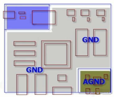
Q: When there are multiple digital/analog functional blocks in a PCB board, the conventional practice is to separate the digital/analog grounds and connect them at one point. In this way, the ground on a PCB board will be divided into multiple blocks, and how to connect them to each other is also a big problem. However, some people use another method, that is, while ensuring that the digital/analog layout is separated and the digital/analog signal routing does not cross each other, the entire PCB board ground is not divided, and the digital/analog ground is connected to this ground plane. What is the reason for doing this? Please advise.
A :The reason for separating the digital/analog grounds is that when the digital circuit switches between high and low potentials, noise will be generated in the power supply and ground. The size of the noise is related to the speed of the signal and the size of the current. If the ground plane is not divided and the noise generated by the digital area circuit is large and the analog area circuit is very close, even if the digital and analog signals do not cross, the analog signal will still be interfered by the ground noise. That is to say, the method of not dividing the digital and analog ground can only be used when the analog circuit area is far away from the digital circuit area that generates large noise. In addition, the requirement that the digital and analog signal lines cannot cross is because the return current path of the slightly faster digital signal will try to flow back to the source of the digital signal along the ground near the bottom of the line. If the digital and analog signal lines cross, the noise generated by the return current will appear in the analog circuit area.
21. Circuit board design and EMC!
Q: If EMC is considered in circuit board design, it will definitely increase a lot of costs. How can I A the EMC requirements as much as possible without bringing too much cost pressure? Thank you.
A: The cost increase on the PCB board due to EMC is usually due to the increase in the number of ground layers to enhance the shielding effect and the addition of ferrite beads, chokes and other high-frequency harmonic suppression devices. In addition, it is usually necessary to match the shielding structure on other mechanisms to make the entire system pass the EMC requirements. The following are just a few tips for PCB board design to reduce the electromagnetic radiation effect generated by the circuit.
1. Try to use devices with slower signal slew rate to reduce the high-frequency components generated by the signal. 2. Pay attention to the placement of high-frequency devices and do not place them too close to external connectors.
3. Pay attention to the impedance matching of high-speed signals, the routing layer and its return current path to reduce high-frequency reflection and radiation.
4. Place enough and appropriate decoupling capacitors on the power pins of each device to mitigate the noise on the power layer and the ground layer. Pay special attention to whether the frequency response and temperature characteristics of the capacitor meet the design requirements.
5. The ground near the external connector can be properly separated from the ground layer, and the ground of the connector can be connected to the chassis ground as close as possible.
6. Ground guard/shunt traces can be appropriately used next to some particularly high-speed signals. But pay attention to the impact of guard/shunt traces on the characteristic impedance of the routing.
7. The power layer is 20H inward of the ground layer, where H is the distance between the power layer and the ground layer.
22. GSM mobile phone PCB design
Q: What are the requirements and techniques for GSM mobile phone PCB design?
A: The challenges in mobile phone PCB design are two places: one is the small board area, and the other is the RF circuit. Because the available board area is limited, and there are several circuit areas with different characteristics, such as RF circuit, power circuit, voice analog circuit, general digital circuit, etc., they all have different design requirements.
1. First of all, RF and non-RF circuits must be properly separated on the board. Because the RF power supply, ground, and impedance design specifications are stricter.
2. Because the board area is small, blind/buried vias may be needed to increase the routing area.
3. Pay attention to the routing of the voice analog circuit, and do not cause crosstalk with other digital circuits, RF circuits, etc. In addition to increasing the routing spacing, ground guard trace can also be used to suppress crosstalk.
4. Appropriately divide the ground layer, especially the ground of the analog circuit should be paid special attention to, and do not be interfered by the ground noise of other circuits.
5. Pay attention to the return current path of the signal in each circuit area to avoid increasing the possibility of crosstalk.
24: What issues need to be paid attention to in PCB design?
A: The issues that need to be paid attention to in PCB design vary with the application products. Just like the areas that need to be paid attention to in digital circuits and simulation circuits are different. The following are just a few principles to pay attention to.
1. The decision of PCB stacking; including the arrangement of power layer, ground layer, routing layer, routing direction of each routing layer, etc. These will affect the signal quality and even electromagnetic radiation problems.
2. The routing and vias related to power and ground should be as wide and as large as possible.
3. Regional configuration of circuits with different characteristics. Good regional configuration has a considerable impact on the difficulty of routing and even signal quality.
4. It is necessary to set DRC (Design Rule Check) and test-related designs (such as test points) in conjunction with the manufacturing process of the production factory. Other electrical-related issues that need to be paid attention to are absolutely related to circuit characteristics. For example, even if they are all digital circuits, whether to pay attention to the characteristic impedance of the routing depends on the speed of the circuit and the length of the routing.
23: What issues should be paid attention to in PCB design?
A: The issues that need to be paid attention to in PCB design vary with the application products. Just like the areas that need to be paid attention to in digital circuits and simulation circuits are different. The following are just a few principles to pay attention to.
1. The decision of PCB stacking; including the arrangement of power layer, ground layer, routing layer, routing direction of each routing layer, etc. These will affect the signal quality and even electromagnetic radiation problems.
2. The routing and vias related to power and ground should be as wide and as large as possible.
3. Regional configuration of circuits with different characteristics. Good regional configuration has a considerable relationship with the difficulty of routing and even signal quality.
4. DRC (Design Rule Check) and test-related designs (such as test points) should be set in accordance with the manufacturing process of the production factory. Other electrical-related issues that need to be paid attention to are absolutely related to circuit characteristics. For example, even if they are all digital circuits, whether to pay attention to the characteristic impedance of the routing depends on the speed of the circuit and the length of the routing.
24. Regarding EMC and EMI issues in high-speed PCB design
Q: When designing high-speed PCBs, the software we use only checks the set EMC and EMI rules. From which aspects should designers consider EMC and EMI rules? How to set the rules? I use the software of CADENCE.
A: Generally, EMI/EMC design needs to consider both radiation (radiated) and conduction (conducted). The former belongs to the higher frequency part (>30MHz) and the latter is the lower frequency part (<30MHz). So we can't just pay attention to the high frequency and ignore the low frequency part.
A good EMI/EMC design must consider the device location, PCB stacking arrangement, important connection routing, device selection, etc. at the beginning of the layout. If these are not arranged better in advance, solving them afterwards will be counterproductive and increase costs. For example, the location of the clock generator should not be close to the external connector as much as possible, high-speed signals should be routed on the inner layer as much as possible and pay attention to characteristic impedance matching and continuity of the reference layer to reduce reflection, the slew rate of the signal pushed by the device should be as small as possible to reduce the high-frequency component, and when selecting decoupling (decoupling/bypass) capacitors, pay attention to whether its frequency response meets the requirements to reduce the power layer noise. In addition, pay attention to the return path of the high-frequency signal current to make its loop area as small as possible (that is, loop impedance as small as possible) to reduce radiation. You can also use the method of splitting the ground layer to control the range of high-frequency noise. Finally, choose the grounding point (chassis ground) between the PCB and the shell appropriately.
26. About the impedance matching problem in PCB design
Q: In high-speed PCB design, impedance matching must be considered to prevent reflection. However, since the PCB processing technology limits the continuity of impedance and simulation cannot be simulated, how to consider this problem when designing the schematic diagram? In addition, regarding the IBIS model, I don’t know where to provide a more accurate IBIS model library. Most of the libraries we downloaded from the Internet are not very accurate, which greatly affects the reference of simulation.
A: When designing high-speed PCB circuits, impedance matching is one of the design elements. The impedance value has an absolute relationship with the routing method. For example, whether it is on the surface layer (microstrip) or the inner layer (stripline/double stripline), the distance from the reference layer (power layer or ground layer), the routing width, the PCB material, etc. will affect the characteristic impedance value of the routing. In other words, the impedance value can only be determined after routing. Generally, simulation software cannot take into account some impedance discontinuity wiring conditions due to the limitations of the line model or the mathematical algorithm used. At this time, only some terminators (terminations), such as series resistors, can be reserved on the schematic diagram to mitigate the effect of impedance discontinuity. The real fundamental solution to the problem is to try to avoid impedance discontinuity during wiring.
The accuracy of the IBIS model directly affects the simulation results. Basically, IBIS can be regarded as the electrical characteristic data of the actual chip I/O buffer equivalent circuit, which can generally be converted from the SPICE model (measurement can also be used, but there are more restrictions). The SPICE data is absolutely related to chip manufacturing, so the same device provided by different chip manufacturers has different SPICE data, and the data in the converted IBIS model will also vary accordingly. In other words, if the device of manufacturer A is used, only they are able to provide accurate model data of their device, because no one else knows better than them what process their device is made of. If the IBIS provided by the manufacturer is inaccurate, the only fundamental solution is to constantly ask the manufacturer to improve.
27. Comparison of PCB design tools
Q: In your personal opinion, which EDA tool has the best performance-price ratio (including simulation) for analog circuits (microwave, high frequency, low frequency), digital circuits (microwave, high frequency, low frequency), and analog and digital mixed circuits (microwave, high frequency, low frequency) in PCB design? Can you explain them separately?
A: Due to my limited understanding of applications, I cannot compare the performance-price ratio of EDA tools in depth. The selection of software should be based on the scope of application. The principle I advocate is that it is enough.
For conventional circuit design, INNOVEDA's PADS is very good, and there is simulation software for matching, and this type of design often occupies 70% of the application occasions. When doing high-speed circuit design, analog and digital mixed circuits, the Cadence solution should be a software with better performance and price. Of course, Mentor's performance is still very good, especially its design process management should be the best.
The above views are purely personal opinions!
28. About digital/analog separation layout and intelligent layout
Q: When there are both RF small signals and high-speed clock signals in a system, we usually use digital/analog separation layout to reduce electromagnetic interference through physical isolation, filtering and other methods. However, this is of course not conducive to miniaturization, high integration and reducing structural processing costs, and the effect is still not necessarily satisfactory, because whether it is digital grounding or analog grounding point, it will eventually be connected to the chassis ground, so that the interference is coupled to the front end through the ground. This is a very headache problem for us. I would like to ask experts for measures in this regard.
A: The situation where there are both RF small signals and high-speed clock signals is more complicated. The cause of interference needs to be carefully analyzed and different methods should be tried to solve it accordingly. According to the specific application, you can try the following methods.
0: When there are RF small signals and high-speed clock signals, the first thing is to separate the power supply. It is not appropriate to use a switching power supply. A linear power supply can be used.
1: Select one of the RF small signal and high-speed clock signal, and use a shielded cable to connect.
2: Connect the digital grounding point to the power ground (the power supply isolation is required to be good), and the analog grounding point to the chassis ground.
3: Try to use filtering to remove interference


