To ensure reliability and efficiency of operation, heat must be removed from the power components that generate heat. Thermal management helps to elicit heat from the components of the heating system in a variety of application industries.
Rocket PCB provides a variety of thermal management PCB types, including farm radiator/tray, radiator coin, embedded coin, electronic coin, pressed fit coin, metal inlay, solder, or adhesively connected through holes. In addition, Rocket's thermal management solutions include our patented embedded E-coin technology, radiator coin accessories, and thick copper. We focus on RF and microwave.

More than 50% of electronic system failures are caused by runaway heat. Let the statistics sink in for a while, and then give it some logical thinking. If we can implement good thermal management, we can significantly reduce the number of electronic system failures. Well. . . It seems worth some time and effort.
During the internal movement of PCB, electricity will produce a lot of heat more or less, depending on the resistance it encounters. Besides wiring, power components, such as MOSFET, IGBT, converter, and driver, are also the main cause of heat generation. Although the power supply voltage of highly integrated logic devices such as DSP, SOC, and FPGA is gradually decreasing, due to the high working frequency and the extensive use of highly complex algorithms, these devices will also produce heat that can not be ignored. Thermal management is one of the most critical and insidious aspects of PCB design. On the one hand, to ensure the correct operation and reliability of the circuit, every voltage, current and allowable frequency value should be determined. On the other hand, the budget constraints imposed by manufacturers must be respected, limiting the use of cumbersome and expensive cooling solutions, such as radiators, fans, or liquid cooling. Therefore, not only in high-performance applications, full thermal management is of core importance. This should be designed separately for each specific application and the environmental conditions of the entire system.
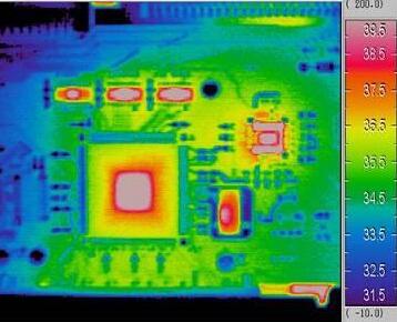
Basic considerations of thermal management
As the carrier of components, printed circuit board (PCB) is the main component to realize continuous thermal management. In the future, insufficient optimization must be compensated by measures that may increase the cost.
In advance, the following basic factors should be considered:
· What heat (power loss) must be removed from where?
· What are the dimensions and performance data of the components?
· Where is the heat source (such as LED) on PCB?
· Free space and peripherals?
· Application temperature and ambient temperature?
· What mechanism is used to cool the system(Temperature drop)
· How should heat be transferred to the radiator?
· Are there any reliability requirements (e. g. cycle stability)?
Due to the low thermal conductivity (0. 2-0. 5 w/mk) of FR4, pure FR4 printed circuit boards are generally not suitable for heat-intensive applications (such as high-power LEDs).
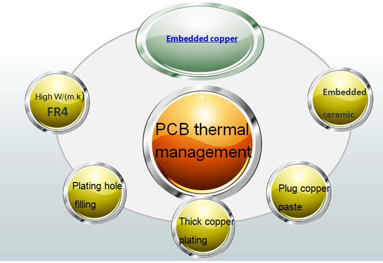
The following PCB thermal management options are available:
Design/build of the printed circuit board
Thick copper PCB
Thermal via array
Metalcore
Embedded copper coin/copper block technology
Design/build of the printed circuit board
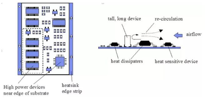
Due to the extensive use of QFP, BGA, and other surface-mounted components, a large amount of heat generated by the components is transferred to the PCB board. Therefore, the best way to solve the heat dissipation is to improve the heat dissipation capacity of the PCB itself which is in direct contact with the heating elements. The following options help to limit the heat generation or better heat dissipation:
1. Reasonable wiring design for heat dissipation
2. When PCB layout technology alone can not meet the thermal management objectives, designers may consider higher-cost solutions. High-Performance PCB materials and functional components can help the overall heat dissipation. Rogers laminates meet this requirement, thanks to DK between 6. 15 and 11, while FR-4 provides DK of 4. 5. In addition, the material has high stability when the temperature and frequency change, thus reducing the power loss under all working conditions.
3. Local isolation of high-power and signal conductors shall be arranged according to their calorific value and degree of heat dissipation
4. High power devices should be arranged close to the edge of the PCB
5. Wide orbit of large current
6. Add thermal pad and PCB through-hole to improve thermal conductivity
7. Large-area copper foil surface and higher copper thickness
8. Additional thermal vias
9. High heating device with radiator and heat-conducting plate
10. A thermal simulation or prototype observation can help better locate hot spots.
In a word, please avoid the hot spot concentration on the PCB board, and try to distribute the thermal power equally on the PCB board as far as possible, so as to keep the PCB surface temperature uniform. In the design process, it is usually difficult to achieve strict uniform distribution, but the area with high power density should be avoided.
Thermal Via
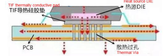
The thermal through-hole is very simple, which is located under the surface mount heat source of the circuit board, and can carry out heat transfer. Simple via or via in pad can greatly reduce the thermal resistance. For PCB Applications with a thickness greater than 0. 70mm, you can also place the vias of the fill and cover directly under the hot pad. Filling the through-hole with epoxy resin and covering it with copper can prevent any uncontrolled solder flow from causing solder flow. In addition, through-holes for filling and capping ensure excellent welding
Thick copper PCB
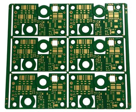
Thick copper circuit board (e. g. 70)μm, 105μm. Up to 400μm) It can improve the heat dissipation so that the heat is distributed on a larger surface. The heat distribution occurs in the copper layer of the PCB surface and inner layer.
Thick copper circuit boards are mainly used for high power (high current) applications and cooling components with high heat dissipation. Note that the maximum conductor width depends on the thickness of the copper.
MCPCB
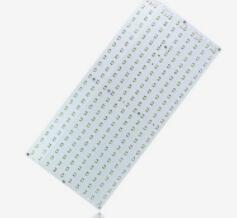
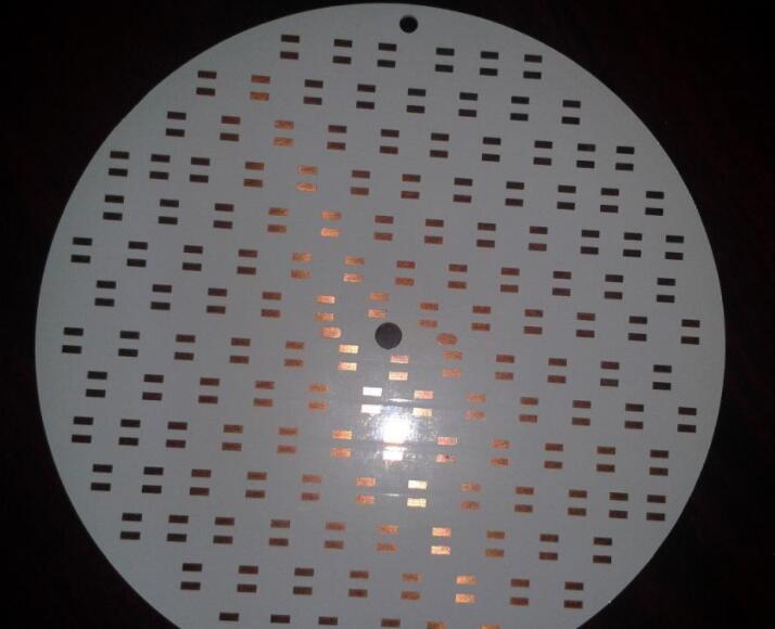
Power components generate a lot of heat. Power modules are used in many PCB Applications, so it is important to configure the circuit board in a safe way. The heat load is most easily dissipated by the use of copper layers, vias placed under power modules, cold walls, thermal pads, and module spacing. The most successful results combine some combinations of these technologies to achieve the best results.
In the case of extensive use of power components or other heating elements, one of the most common ways to prevent PCB overheating is to use PCB with metalcore. Metal core PCB or MCPCB can also be insulated, referred to as insulated metal substrate PCB (IMS PCB) or IMPCB. This includes combining a substrate of material with different thermal conductivity with a metal plane, which is usually made of copper. MCPCB technology uses thermal conductive prepreg placed between PCB layers, which has the function of extracting heat from components and routing it to the metal plane. MCPCB technology can use single-layer or double-layer metal planes (upper and lower layers of PCB), which is widely used in lighting applications with power or high brightness LED.
Metal Substrate PCB material can be aluminum base, copper base, iron-based, and Silicon steel base.
Embedded coin PCB
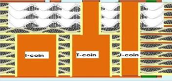
If the heat generated is concentrated in a small number of components, the copper coin can also use technology. Using the high thermal conductivity of copper, the same metal sheet is inserted into the interior or surface of PCB, usually under the high-power components.


