There are many online followers online.
Most of them are made using separate modules.
There are several individual PCB designs to choose from, but in a single PCB design all three features like Bluetooth control, barrier avoidance, and line tracking are not available.
In this instructable, I will share the recipe for my single PCB line follower with Bluetooth controls and barrier avoidance features.
The robot is completely open source and you can easily copy it.
I will provide all the required materials in the following steps, including schematic diagram, PCB design file and Arduino source code.
The Bot is designed as a single PCB and all required components and sensors are placed directly on the PCB without the need to use any breadboards or any individual modules.
Therefore, it is more reliable than other line followers using separate sensor modules.
For line follower, I used the PID controller and you can adjust all three PID parameters from your Android phone, which can reduce a lot of adjustment trouble and also help save a lot of adjustment time.
Before further viewing the demo of the line follower using the PID controller.
The following lines: Power-on-
I used two lithium batteries of 18650.
The Arduino NANO uses the master controller and I place the Nano using the pin head so I can easily remove it from the bot.
If you are interested and plan to continue reading.
Bluetooth control: Components: Tools: Power-
In the circuit, the Arduino Nano board, the op amp, the Bluetooth module, the ultrasonic sensor and the infrared sensor array need 5v to adjust the DC when running, the motor drive IC requires an additional 6v DC to power the motor. Two 3.
The main power supply is 7v lithium battery.
The battery power supply for Arduino and other sensors and ic is adjusted to 5 v.
Pin 1 of the voltage regulator ic is connected to the anode of the battery and pin 2 of the two ICS is connected to the ground.
The DC motors cannot be connected directly to the battery because they can only be controlled by the motor-driven IC, which itself needs to adjust the power input. Arduino NANO -
Arduino NANO is one of the most popular prototype boards.
Because of its small size and rich functions, it is often used in robot applications.
The board is built in
In the Arduino boot loader.
It is an Atmega 328-based controller board with 14 GPIO pins, 6 PWM pins, 6 analog inputs, and on-board asynchronous, SPI, and TWI interfaces.
In this project, the infrared sensor is connected using the 7 GPIO pins of the board, the L293D motor drive IC is connected using 6 GPIO pins, and the ultrasonic sensor uses two GPIO pins, the Bluetooth module uses two GPIO pins.
DC motor drive IC-L293D
L293D is double H-
Integrated Road and Bridge motor driver (IC).
Since the motor drivers feature low current amplifiers, they act as current amplifiers
Current control signal for Arduino and provide higher-
Current and higher voltage signals.
The current signal used to drive the motor is high.
Pins 4, 5, 13 and 12 of the L293D IC are grounded, pins 1, 16 and 9 are connected to 5v DC, and pin 8 is directly connected to the battery.
Pins 15, 2, 7 and 10 of this motor driver IC are connected to pins 5, 2, 3 and 4 of the Arduino board.
The DC motor connected to the right wheel is connected to pins 11 and 14, while the motor connected to the left wheel is connected to pins 3 and 6 of the motor-driven IC.
Pins 15, 2, 7 and 10 are the input signal pins for the motor driver IC.
These pins are connected to the Arduino pins.
When changing the digital logic on the Arduino pin, the logic on the motor driver IC input pin will also change.
As shown in the above table, the direction of rotation of the DC motor depends on the digital logic on the motor drive IC input pin.
DC motor
In this robot, the 6v micro metal deceleration DC motor (N20)
Connected to the wheel.
The gear DC motor has a wide range of RPM and torque, which enables the robot to move according to the control signal received from the motor drive IC.
The maximum speed of the motor used here is 400 RPM.
Infrared sensor array
The design of the line follower is along the black line.
For this purpose, a sensor is needed that can detect the color of the lower surface.
Infrared sensors can detect the color of the lower surface based on reflection/non-reflection
Indirect incidence of reflex
The infrared LEDs emit infrared radiation, which in normal condition is reflected back from the white surface around the black line.
Reflected radiation is detected by a photoelectric diode.
However, when the infrared radiation falls on the black line, it is completely absorbed by the black, so the infrared radiation does not reflect back to the sensor module.
In this way, the black bars can be detected by the infrared sensor module.
The infrared sensor has analog output and digital output.
In this robot, the sensor module is designed using an infrared sensor with a digital output.
The sensor model is LTH1550-01.
Variable resistance-
A multi-turn variable resistor is used in the sensor circuit to form a resistor divider.
The VCC is applied on the variable resistance side, so the output of the voltage divider is proportional to the resistance of the variable resistor and inversely proportional to the resistance of the corresponding photoelectric diode.
The use of variable resistors allows calibration of sensor circuits to detect black bars correctly. LM324N OPAMP -
LM324N is used to add an op amp to a circuit.
LM324N is a universal four-way operational amplifier (Op-Amp).
In the circuit, OPAMs is used as a voltage comparator.
The output from the variable resistor is used as the reference voltage input of the comparator.
The output of the infrared sensor is used as the input of the comparator.
Based on color, the comparator generates digital output for Arduino.
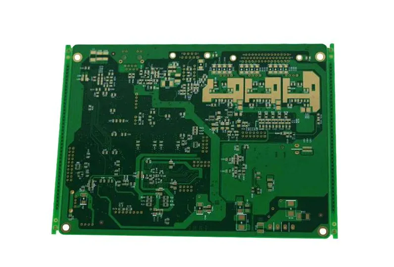
The complete circuit was designed on the Eagle and the schematic and BRD files were attached at the end of the step.
First of all, you need to design your motherboard.
I use Eagle CAD but it can be any other PCB design tool.
The PCB layout is designed for a double layer and I would suggest using vias as little as possible as this will reduce the amount of work later.
It is recommended to install holes around the corner.
Even if you don\'t need them, they make it easier to align layers.
Once done, you can print your design on smooth paper.
I suggest using paper.
Remember to use the maximum Toner density and resolution and must maintain the scale factor 1.
For the top layer, print the design as a mirror reflection.
Including mesh, through hole, pad and hole.
In Eagle I added the dimension layer to make it easier to cut the board.
When printing the bottom, make sure that the mirror check box is not selected.
Otherwise, you end up with a print that needs to be transferred via paper.
It may be difficult.
For the ground floor, including mesh, size, pad and hole.
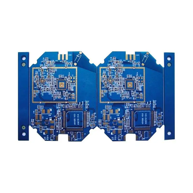
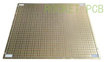
The design size is 4 inch x 5 inch. So, a dual-
Two-sided 4 inch X 5 inch copper-clad board is required for
PCB manufacturing.
I choose double-
Double-sided fiberglass copper clad plate.
Make double-the hardest part
The manual double sided PCB perfectly aligns the top and bottom layers.
The toner transfer method is an easy way to make a pcb, as all you need is a printer, iron, some laminate and etching agent.
However, if your design needs two layers, your challenge is to align them.
If this fails, your vias will not be able to connect the layers correctly.
You may also encounter a situation where you can drill a mat on one side but a net on the other.
For more information on hand-made two-sided PCB, please see this excellent tutorial: self-made two-sided PCB
Layered PCB with toner transfer method.
I will create a double
So I need to include some reference points that match on both sides.
It\'s a good idea to include the PCB edges, but you can also place some extra marks outside the PCB area.
This will make it easier to verify that the pattern is still aligned once you clip the PCB between them.
You can slightly reduce the need for perfect alignment by making the \"via\" pads on one side a little larger and not drilling holes on the pads.
If the copper of the PCB looks a bit oxidized, you might want to clean it with a little vinegar first (
Or a stronger acid like HCl)
This will return the metal to the United Nations. oxidized state.
Scrub the copper side with a grinding pad until the copper is shiny and clean.
Next, scrub the copper side with a paper towel soaked in acetone.
This step is essential!
Acetone removes residual dirt and grease.
If there\'s anything left on copper, the toner won\'t stick well in those places.
You should rub hard on copper per square millimeter and replace the cleaning part of the towel regularly.
Repeat until there is no more dirt on the towel.
Needless to say, you have to avoid contact with copper after this step. Double-
Layered boards are tricky.
The safest way is to first transfer one side and secure the other side with tape or foil etching.
Also drill at least a few holes to make alignment easier.
Then transfer and etching the other side (
Again, cover the side that has been etched).
Faster but more difficult is by clamping the pcb between two sheets of paper and making two transfers at the same time.
In this case, there may be problems with alignment.
What can work is to align two sheets of paper in advance.
Place them in bright light and once aligned, stick one or two edges together or bind them together.
You can then insert the board into the middle and iron both sides clean.
Adjust the iron to the highest position.
Put the PCB, copper side up, put it on the heat-
Resistant to surface.
Wood gets darker in one place if you don\'t mind.
Put the design in copper (
Obviously, the toner face down)
, Align correctly.
Then, while making sure the paper is not displaced, place the iron on it.
Press hard and move the iron every 5 seconds or so to make sure the whole board is heated evenly.
Next, you should rub the whole board with the side and tip of the iron.
Keep the iron slightly tilted, so most of the pressure is concentrated at the tip.
This piece of paper should shine where you have already wiped it so you can see which areas you will need to cover as well.
It\'s OK if the paper gets a little brown throughout the process, it just means you\'re really heating it, which is fine.
It takes some experience to find the right pressure you need: too little pressure can lead to bad transfer, too much pressure will lead to Toner application.
Don\'t expect your first PCB to be perfect!
Details: etching the bottom copper is now the time to align the top to the board.
To do this, I made three holes on the board and placed the copper print on the top according to the hole to make it match perfectly.
Then I transferred the toner.
Before etching the top layer, I use the tape again to make the etched bottom layer musky to protect the layer from etching anymore.
After flushing and drying the PCB, you can choose to remove the toner immediately or wait for all other steps.
Removing the toner is a bit easy before drilling, but in the next steps, keeping the toner open will protect the copper.
Whenever you want to do this, wipe the toner with acetone with a wet towel.
After fine grinding the bottom of the early etching, I sank the iron chloride solution into the top layer of the plate etching.
It takes about 15 minutes to completely etching the PCB.
After etching both sides, you need to make holes for the pads and holes.
No matter what etchant you use, you should wear safety gloves because you don\'t want to get any substance that dissolves metal on your skin.
Safety goggles are also a good idea to prevent accidental spills into your eyes.
Obviously you can\'t use metal containers for etching.
Especially aluminum containing HCl
Unless you are eager to get into huge trouble, it is a very, very bad idea based on etchant.
If you want to know why, pour a little bit of HCl in the glass jar in the well
Ventilation area, put an aluminum foil ball inside. Enjoy!
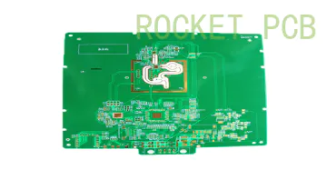
To place the wheel, you need to cut both sides of the PCB according to the mark.
43mm standard wheel marked as micro metal gear motor.
You can cut the PCB using the hack saw or the mini Dremel tool. Lots of hassle! Is not it?
I don\'t like the trouble?
JLCPCB can eliminate all the trouble at very low cost. JLCPCB (
Shenzhen jialichuang Electronic Technology Development Co. , Ltd. , Ltd. )
Is the largest
PCB prototype enterprise in China and
Technical manufacturer specializing in the production of fast PCB prototypes and small PCB
Mass production of PCB.
JLCPCB has more than 10 years experience in PCB manufacturing, more than 200,000 customers at home and abroad, more than 8,000 PCB prototype online orders and a small amount of PCB production every day.
The turnaround time for JLCPCB is very fast.
Just submit your grab and let them verify your design.
I hope you can get feedback within 24 hours.
Pay, wait a week, get the PCB.
The next step is drilling holes and holes as we have not been using SMD components all the time.
For most common components such as resistors, IC, and pin head holes, a 0. 8mm (1/32\")
The drill is perfect.
The big hole can be 1mm (1/25\")or 1. 2mm (3/64\").
If you don\'t need to drill a lot of holes, a normal hs drill is fine.
If you are careful enough, you can drill holes by hand, but the drill bit will make your life easier and reduce the risk of breaking fine pieces.
If you need the drill to be very porous, you may want to look for the carbide drill bit as the glass fiber board will wear the highway drill bit very quickly.
Be careful: these are very brittle, so there must be a stable drill bit here.
To improve the appearance of the PCB and make it easier to weld, you can print the assembly drawing on the Assembly side, just like transferring toner on the copper side!
This is much easier because the toner rod is notcopper side.
There is no need to waste smooth paper on this, just plain office paper.
Remember to mirror before printing.
Scrub the surface with acetone (
No need to use grinding pads)
, Clear any dirt in the hole and use the drilling alignment pattern to keep the plate in line with the bright light.
Then, iron as usual and soak the board in the water.
Just peel it off and the toner should stick hard enough.
Remove any remaining paper with a toothbrush.
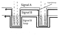
After drilling, I use the resistance lead of vias to connect the copper trace at the top and bottom.
I use resistance leads for all vias.
After making vias, I welded the IC base for all three ICs (
One L293D and two LM324N).
It is a good practice to use the ic base without directly welding the IC to the circuit board.
It can provide you with several advantages, such as preventing burning IC during welding, debugging any faults and easily replacing the faulty ic.
Then for the same reason, I used the female guide in the Arduino NANO.
I then welded all the other components such as sensors, resistors, LEDs and voltage regulators.
I used the female guide rail on the Bluetooth module and the ultrasonic sensor.
Finally, I use the brackets and screws to place the motor in the correct position and weld the motor lead on the correct pad.
Unlike sensors, all components are placed on top.
Five lines following the sensor are placed at the bottom of the board.
Green LEDs are used to observe sensor output.
The battery box is welded directly to the circuit board and the SPDT switch is used for on/off functions.
A simple line follower robot tries to keep the robot along the center of the black bar by detecting black bars using an infrared sensor module and moving the robot left or right.
When an infrared sensor array is used, the average value of the infrared sensor output is used to accurately locate the position of the robot along the strip center.
The simple line follower without any feedback mechanism is not very stable.
The closed-loop PID controller greatly improves the stability of the system.
PID algorithm is implemented in Arduino sketch.
The algorithm is used to control the duty cycle of PWM applied on the IC input pin of the motor driver.
Therefore, the variable controlled in the PID implementation is the duty cycle of the PWM, expressed by the power
Differences in program code.
In each iteration of the controller program, the duty cycle changes depending on the proportion of variables, derivatives, and integral times the constant Kp, Kd, and Ki.
By moving the calibration robot in the center of the strip, the constant is derived.
In order to export the constant, in the program code, try a different value of the constant starting from the zero value of each constant.
An android program was developed for car tuning purposes.
The value of the scale variable depends directly on the current position of the robot exported by the reference strip center.
The position of the robot along the center of the strip is derived as a negative integer or a positive integer through the sensor value.
So the code determines whether the robot should turn left or right.
The value of the derivative variable is the difference between the current value of the proportional variable and the value of the proportional variable in the last iteration of the code.
This gives the difference with the desired output.
The value of the integral variable is the sum of the value of the variable in the previous program code iteration and the current value of the proportional variable.
Using all three variables multiplied by their respective constants, the power difference or the upcoming difference in the PWM output is derived and corrected according to the duty cycle of the PWM output.
PID algorithm is implemented in Arduino sketch.
The PID algorithm is implemented using three constants Kp, Ki and Kd.
They are shorthand symbols of proportions, integral, and differential constants, respectively.
These three constants must be set after testing and need to be defined for the desired control application.
In order to implement a simple PID control algorithm, first of all,)
The function is used in the code to read the value from the infrared sensor.
Calculate the error according to the sensor reading.
Calculate the PID value from the calculated error.
The process of setting the optimal gain for P, I, and D to obtain the ideal response from the control system is called tuning.
The goal of setting the PID loop is to make it stable, responsive, and minimize overtuning. These goals -
Especially the last two.
Conflict with each other.
You have to find a compromise between acceptable goals to meet all of them.
Process Requirements and physical constraints will determine the balance between acceptable overshoots and response requirements.
There are different tuning methods, including the \"guess and check\" method and the Ziegler Nichols method.
The gain of PID controller can be obtained by trial and error method.
Once the engineer understands the importance of each gain parameter, this approach becomes relatively easy.
In this method, the I and D terms are first set to zero and the proportional gain increases until the output oscillation of the loop.
The system becomes faster as the proportional gain increases, but it is important to be careful not to make the system unstable.
Once P is set to obtain the desired fast response, the integral term is increased to stop the oscillation.
The integral term reduces the steady-state error, but increases the overshoot.
A certain amount of overtuning is always necessary for a fast system so that it can respond to changes immediately.
In order to achieve the minimum steady-state error, the integral term is adjusted.
Once P and I are set to obtain the required fast control system with minimal steady-state error, the derivative term increases until the loop is able to quickly reach the set point.
Increasing the derivative term reduces overshoot and gains a higher gain in a stable condition, but causes the system to be highly sensitive to noise.
Often, engineers need to weigh a feature of the control system to better meet their requirements.
As mentioned earlier, the best way to define the correct constants used by the PID controller is to use \"Try-
Error \"method.
The bad thing is, you have to re-
Compile the program every time it has to be changed.
One way to speed up this process is to use the Android app to send constants to the car, observe the response and record the values that match perfectly.
The application uses MIT app Inventor as well as source files and.
The apk file is attached below.
In order to drive the car, I used the Arduino Bluetooth RC car provided by the Game Store for download.
You did the previous steps and congratulated you! ! ! .
You have succeeded in making your own robot, which has a lot of features including following the line and looks as cute as the picture above.