What impact will the 2024 PCB factory bankruptcies have in 2025?
PRODUCTS
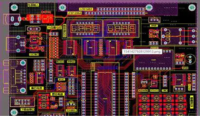
How to Make PCB at Home Using a Laser Printer
by:Rocket PCB
2020-04-24
As an enthusiastic electronics hobby fan I was always fascinated by the fact that it is actually possible to make an almost professional looking Printed Circuit Board (PCB) at home. My eager for producing my PCB's at home rather than using the good old wire-wrap prototyping method gets even stronger as the years goes by and the availability of through hole packages (for modern devices) is getting lower and lower. When thinking of a new design, one has much more devices to select if SMT technology is acceptable. That is a very strong motivation to learn about making your own SMT PCB at home. The method I'm going to introduce here has great success rate and beautiful results. It is important to follow the rules. It is truly a production process that once completed makes you feel really proud of accomplishing it. Again, following the rules is crucial for the success of the process. This may sound intimidating at first, but actually, the process is very easy to follow. Major production steps: 1. Prepare a mirrored image of your circuit, printed on a toner transfer paper using a laser printer. 2. Cut, sand and clean a piece of copper over glass epoxy laminate. 3. Bake your piece of art in the oven. 4. Etch your board inside an etching chemical. 5. Rinse in water and sand some leftovers. 6. Show everybody your board. 7. Solder the components. Few notes: Don't forget to take safety measures when doing these steps. It is highly recommended to use latex gloves when handling the etching chemical. During the production process there are many opportunities to cut yourself, ruin your clothes, burn your fingers and inhale unfriendly substances. Use caution. Well, lets get started ! Like every product in the modern age, your PCB would start in a design software on your PC. Choosing your favorite design software for this task is out of the scope of this document. The only requirement that I insist of is being capable of printing an image of the design in a mirror view. The importance of mirroring the design is hard to explain in words and should be understood from the pictures followed at the link below. The great advantage of an SMT based PCB for home production is that SMT devices do not require drilling holes threw the board. That's just great. However, sometimes you can't get away with this. There are few cases which force you to drill holes. for example, few connectors require drilled holes. Traces that could not be routed in copper and require soldered bridging between two points would also require drilling. Any way, SMT technology reduces dramatically the amount of drilled holes while shrinking the board size at the same time. The reason I discussed SMT advantage was to make you keep in mind while designing your circuit, that you want minimum amount of drills and you should try to avoid complex designs at the first place. I always try braking large circuits into few separated boards. There are two major reasons for this board segmentation. First, The smallest the circuit the easiest the layout. Second, smaller circuits may serve as basic general purpose building blocks for larger designs in the future. Think of a general purpose operational amplifier board. Such board may have only an OPAMP device with few resistors around it and soldering points for connecting external wires. It is a great building block for many projects. Once your layout design is ready for production, you should be able to print a mirrored image of it using 1:1 scale, on a special glossy paper (Toner Transfer paper would be best), using a laser printer. Lets brake the previous sentence into smaller pieces now. A finished design should look like a graphical representation of the traces that should reside on the finished board. The image must be mirrored because of the way we are going to use it later in the process. Now, Glossy paper is a general term for a more confusing definition like 'Some paper used by ink jet printers for photo printing'. Just in case you didn't know, Not all photo papers were born equal. Finding the right paper for this job may be tedious. The first paper I used could not be peeled off the PCB at the end of the process and I had to throw it away. The next paper I found was a hit. It peels easily and leaves a clean print of the traces over the bare copper. I will discuss this peeling issue later in the process. Remember that you may try few photo papers before you find the 'one'. Don't get give up right away. Luckily enough, there are special Toner Transfer Papers designed exactly for this purpose. Using 1:1 scale means that you should set your software to print the image of your board with dimensions equal to the real dimensions of your components and traces. And finally, only laser printing would do the trick. That is because the Toner, which is the black substance (laser 'ink') used for laser printing is actually a polymer that does not soak into the paper like real ink. The Toner is heated inside the printer and when it melts it sticks to the surface of the glossy paper. Stuck to the surface of paper, the Toner just waits for an opportunity to stick (be transferred) to other surface if it gets hot enough to melt. Are you starting to get it? Now that we have a printed version of our PCB in hand, we would cut the paper to the outlines of our board and leave few more millimeters of paper on the edges of the board. This leftover outside the outlines of the board will be used later as a grip point for peeling the paper. This is the part where get our hands dirty by doing some craft work. A PCB starts as a laminate of a thin copper layer over a glass epoxy substrate (also called FR4 laminate). Laminates can be usually found where you'd buy your electronic components. There are two types of laminates for the home user. Single sided and Dual sided. usually 1mm to 2mm thick. Single sided means that there is copper only on one side of the laminate. Dual means there is copper on both sides of the laminate. This paper focuses on single sided PCB's so single sided laminate is good enough. Single sided circuits can be made of single or dual sided laminates because either way any unwanted copper is etched away. Cutting the laminate to the circuit size is done in two phases. First, you mark the height of your circuit across the laminate using a sharp knife and a ruler. The deeper the marking the easiest it is going to be. After marking the line, you should align the straight line with an edge of a table and place a ruler above the laminate. Applying pressure on the laminate should brake it across the marking leaving a nice straight edge. Now, the width of the circuit should be marked and cut at the same way. Now that we have the laminate cut to the size, we should prepare it for the toner transfer process. Using the finest sandpaper (wet paper) the copper should be sanded evenly until the copper is clean and shiny leaving microscopic scratches on the copper surface. These microscopic scratches are best as gripping points for the sticking of toner to the copper. After sanding the copper it is important to wash the laminate with soap. Using kitchen dishes soap would be best. This washing is intended to remove any grease leftovers (fingerprints are greasy too). Grease leftovers would prevent proper sticking of the toner to the copper. Avoid touching the copper after washing it because it should be kept grease free (fingerprints are greasy). Finally the laminate should be dried using a paper towel. Do you remember the mirror printed image on a glossy paper? place it above the dry copper such that the copper is facing up and the toner is faced down towards the copper. The paper should lie straight above the copper. Hold the paper and laminate steady and use adhesive tape on two edges of the laminate to hold the paper and laminate together. Make sure the circuit is aligned the way you want and take a deep breath because the most interesting step is next. Your circuit is now ready for the baking stage. Few people recommend ironing the paper using a hot iron until it sticks to the copper. The problem I found with ironing was that it is not predictable in terms of toner transfer succes. Some times it works and some times it doesn't. I believe that I developed a better technique. Before baking can start you should prepare some sort of pressing device that would keep the glossy paper pressed onto the copper. I use two thick aluminum plates with holes at the corners. Bolts are used to attach the plates together while the circuit is in the middle. The circuit must be cushioned between thick layers of paper. The cushioning is important to spread the pressure across the laminate and prevent some areas of the circuit from not being transferred properly. The bolts and nuts should be closed quite strong to apply great pressure over the laminate and glossy paper match. The press should be inserted into a preheated 150 degrees Celsius oven for a period of about half an hour. The baking time may vary depending on the mass of the press device you use. The heavier the press the more time it gets to get hot enough in order to transfer the heat to the paper cushioning and the circuit within. After baking is finished it is recommended to turn off the oven, open the door and let it cool until you can safely touch the press device with your hands. This is the time to loose those bolts and find your circuit between the layers of paper. If everything went OK you should see that the glossy paper is stuck to the copper. Now find an edge of the paper and start pulling it gently away from the copper. If you had some luck, the paper comes off rather easily leaving a nice print over the copper. If the paper is not a friendly one you might have real difficulties with peeling it away without ruining the printed traces on the copper. Sometimes, if the pressure wasn't applied evenly across the board you would see that some toner does not stick to the copper and the laminate is now useless for the next stages (can be sanded and started from the beginning). If nothing went wrong you should now hold in hand a laminate with your circuit printed on it just like as if it was a piece of paper that came out of a laser printer. Just before etching is started, You may go on drilling few holes now for through hole packages and bridging wires if needed. It is preferable to drill before etching is started because the surrounding copper gives better mechanical strength to round pads around the drilled holes. These pads may be ripped off sometimes when drilling after the board is etched. Another good reason is that the etching after drilling would remove any strands of copper around the edges of the drilled hole. Now is the time to remove unnecessary copper where there are no traces (no toner). The toner is actually a protective layer that prevents the etching fluid from etching our traces. The etching substance is called Ferric-Chloride and it can be bought as little gravel or in powder form. The etching fluid is a mixture of warm water (just like the temperature you would use to wash your hands on a cold day) and Ferric-Chloride. The quantity ratio is not crucial. Too little Ferric-Chloride would slow the etching process. Too much will result in a messy dark mud like fluid. I use ratios like making a cup of coffee. Put just little amount of Ferric-Chloride at the bottom of your container and fill it with water. The etching container should be made of plastic or glass - not metal. For the etching process you need to find a way for continues dropping and pulling the circuit into and out of the fluid. This way any remaining copper that has been etched is washed from the surface and letting the fluid penetrate into deeper layers of copper. I am using something like a small fishing rod with a line connected to a little hole drilled somewhere on the laminate. Once etching was started, it may take few minutes of etching until you see some results. At first, large areas of exposed copper start to disappear. Few more minutes will expose the gaps between traces. Finally after about half an hour or more the board will be finished. At the moment the board looks the way you want, it should be washed under running water to remove any leftovers of the etching fluid and stop the etching process. Use caution when washing the circuit (and the container). Splashes of the dark fluid will stain anything in their way. After the circuit has been washed it is ready for the final stage. Using the finest sand paper again (wet paper), the black toner should be removed to expose the copper. An alternative way to remove the black toner would be washing it with few drops of Acetone. Once all copper is exposed the board is ready for soldering. This is it. You are now holding your first hand made PCB. This is the time to go and show everybody what you achieved. Now, all you have to do is solder your components and turn on your circuit... It is strongly recommended to watch the photos at the following link.
Custom message
Related Products