how to reverse engineer a schematic from a circuit board
how to reverse engineer a schematic from a circuit board
by:Rocket PCB2019-09-09
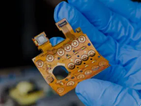
This project is the result of the failure to obtain circuit diagrams due to the need to serve domestic electronic products. It turns out that the process is very long and hard, but it is also very rewarding. The steps presented here are not accurate and there is no doubt that for any particular board you will find yourself working in a more efficient way. However, I think the basic procedure is basically correct for most boards that are too complex to reliably trace their hands. Without the need for an invention process, things should progress faster. For a simple board, it is best to draw the board on square paper using pencil and paper, replace the assembly with symbols, and change the track Cross position to avoid the assembly. For complex circuit boards, it is easy to lose position using this method. The next \"level of complexity\" obtained from a simple, drawable board may be a good candidate for the tracking method described in step 16 of this instructable, it misses all and modifies accordingly. At a higher level of complexity, as shown in this project, I decided that there were too many tracks tracked by hand, unreliable, and used the graphic techniques described. Some of these methods stem from the fact that the photos I took were too uneven and not clear enough. Better photos mean less work. All the edits are done on a laptop running Linux. The main tools Gimp, Inkscape, AutoTrace, and Dia all have Windows versions, but I don\'t know if the utility pstoedit has a Windows version, unfortunately the extra workaround steps need to be. If not, I believe another solution can be found. I also found that completely hidden traces can exist due to this project- In my chart, there is a transistor that is obviously not connected at the bottom, but I can\'t find the connection to it or through the hole. I think it\'s completely hidden to some extent. I am happy to say that after creating the chart I was able to use it to confirm the questionable fault section. Appendix: Since writing this note, I have found something that is \"blind-looking -- Only part of this hole is left. Through the pcb and connected to the internal layer only. The boards I work on here seem to take advantage of these because some components seem to be missing connections. Unfortunately, I believe these are all hidden in SMD pads if there is no de-soldering. So if you end up with a schematic that looks incomplete, that\'s probably the reason. Google \"blind pcb vias\" for more information. You will work from photos and need some software. You need: * a good camera, preferably a tripod * or even lighting- Photos with bad light can lead to a lot of extra work. The flash of the rebound is just good enough. It may be your best choice if you can use the ring flash. * Computer * Internet access, find components (but see note)* Multimeter- Not necessary, but helpful ( Depending on how precise you need to know how the circuit works, the ability to measure the capacitance may prove useful if you are dealing with SMD) * Strong magnifying glass- You may need to check the unrecognizable details in the photo. * Photo editing program. I\'m using the free Gimp, these instructions are Gimp-specific. I also used the vector program Inkscape to clean up the lines. * Program to turn photos into vector lines-drawing. I\'m using free automatic tracking. I chose to track automatically because it has a \"center- The Line \"option, originally to help pick the text in the image, is ideal for the job. However, I found that auto-tracking collects too many details and is useful for general cleanup. * A program that operates vectors. I am using Inkscape for free and these instructions are Inkscape specific. * The program that draws the operation diagram. I use free Dia and come with a good set of component symbols ( But see the warning in Step 18) * Since the current version of Dia is having problems importing svg files, an intermediate program pstoedit is required. * I found that the graphic tablet is a great help, especially for hands Track some tracks. * A lot of time and patience. . . Notes on finding data tables on the Internet. Component data is widely released on the Internet, which is the absolute gospel. However, component marking is not necessarily complete or clear and you should look into the context of the device to ensure that the device is correctly identified. For example, on the board I use in this Instructure, there is an 8-pin chip identified as \"7101. I found a data sheet for photoelectric. Operating isolator Before it is found that it is almost certainly a DC/DC converter, the amplifier, the voltage regulator, and other devices, are confirmed by the inductor connected as shown in the figure circuit. SMD elements have marks that may not be similar to the part number. Several guides have been published on the Internet, and this is one of them: boards, at least a quick brush with a brush. If you don\'t catch them right now, any spots like dirt, hair, etc. must be removed in your photo editor, and there are a lot of them, which can be quite a long time --consuming. If you have a tripod and you can control the lighting, set everything up. You need to light up the most boring picture ever. Depending on the board, it may also have to be very close. Select an ordinary background that is in soft contrast to the board color. Take the time, set up the lens so there is no perspective, or as little as possible, and fill the frame as much as possible. Use RAW mode if available, otherwise just use the highest possible quality settings. Take photos of both sides of the board to make sure the track is in focus. You may find that it is better to take a picture of the board in several parts and take one at a time. Take a few photos with different settings so you can choose the best. If you don\'t have a digital camera, you have to scan your photos. Again, use the highest quality possible. Set the Directory for the project ( I like to name the folder after the device I\'m working on) , Paste all the photos there and copy the photos that will be used to the childfolder - I called me \"work \". Starting with welding- Side of the board ( With SMD though, there won\'t be much welding there). Open the picture in Gimp and save- Something as meaningful as weldingside-clean. Xcf, for example. Flip picture- Otherwise, it will not match the component side. Set the vertical guide rail. If there is a reason for the board Plane, align it, otherwise just use the edge of the plate or the long straight track. Rotate the image slightly to align the plate or ground plane or track all the way down. ( Of course, the level guide may be more effective for you) Set the second vertical guide and a pair of horizontal guides aligned with other edges (or ground- Aircraft or long track)of the board. Using the perspective tool ( Toolbox: right hand side, third tool down) Click on each corner of the board you need to align, and then drag them so that the other edges are parallel to the guide rail. Make a rectangular selection around the board, reverse it, and press delete. This will clear the background. Eliminate any other interference, such as the projection connector, by selecting around the connector and deleting it. For this case, do not use the fuzzy selection tool, just use the rectangle and ellipse tools. You can make a composite choice. Use these to select complex shapes. Use the clone and blur tools to clear any artifacts as needed. To use the clone tool for Gimp, press ctrl when you click on the area you want to clone. A useful tip for vertical and horizontal PCB tracks is to set up a guide where you want to clone. The clone tool will be aligned with the guide. If the track is set to a 45 degree angle, rotate the layer ( Toolbox, line 3rd, tool edge 3rd) 45 degrees, you can use the horizontal and vertical guides again. ( You may need to enlarge the canvas to fit the picture) Through-Rotary plate 45 degrees, put it back. Use the same trick for other known angles. OK, so you have a nice and clean photo to take care. The general idea from now on is that the picture contains a lot of details, most of which you don\'t want. The details you want to keep need to be separated and saved as a discreet image, so the next few steps focus on both ideas. It is worth saving the image as a before you go further. Open it in Inkscape. Click the image to select it and go to the path> trace bitmap. . . Experiment with all the methods to see if you can get an image with a smooth edge of the track. If not, at least you will have a good idea of what you are facing. If you get a clean image, please process it instead of the original one. You still need to pick out the holes and remove the ground plane and substrate, but this should be easier to handle due to the smoothing of the edges of the track. Create a new layer and make sure it is active. This will contain your alignment mark. They are located on separate layers, making it easier to copy to other layers. Place the border in the corner of the board to align the image later. To do this, make a square selection in each corner, and then use the subtraction mode to make another square selection that is the same size but moves a little inward. Fill the selection with the bucket fill tool. I didn\'t do this and found alignment with no corners tricky. Of course, you can use any alignment mark you like, and the corner is exactly what I want. You need a picture of the holes/pads on the board to align the various images, which makes sense when you remove them later. This is especially important if you have already photographed the part of the board. Depending on the board, you may have to find a different technology that suits you. It is probably easiest to draw them in. New transparent layer ( Layer> new layer) And make sure it\'s active. Select a brush of the same size as the mat and click on each brush with the color you like. If the pad is copper on a green board, for example, turn on the channel dialogue and turn off the green and blue channels. With a little luck, you will only look at the mat. If not, you have more work to do. See the next paragraph for details. Go from Visible to Layer> New. Open the blue and green channels. Add a new layer and fill it in red and change the mode of the red layer to darken only. You may want to repeat the process with another red layer. Remove any layers that are no longer used, such as the red layer (s) If you create multiple, the first new visible. If turning off the green and blue channels does not make the holes/pads clear enough, go to the color> component> decomposition. . . Select herpes and click OK. When a new image appears, copy the hue layer and paste it as a new layer ( Edit> paste as> new layer) The image you are working on. It should be at the top. Set its mode to \"subtract \". With good luck, you should now have clearly visible holes, if a bit blurry. Restore the program above. Again, depending on the board you are working on, the exact results will vary. If \"hue\" doesn\'t work for you, try a different breakdown pattern/layer. After activating new from visible layer, use the select by color tool ( Toolbox, the top line, the second line on the right) To select the pad, adjust the threshold as needed. Copy the selection. Create a new transparent layer, set it to active, and paste the selection. ( You need to \"anchor floating selection\" in the layer window \"). Now you can remove everything except the layer with the hole/pad. If this method doesn\'t work well for you, try layers made up of grayscale and inverted copies of the background, layers of different colors, opening and closing channels, and layer blending modes. You may find that if the light is too uneven, you need to use one method in one part of the board and a different method in the other. Select the part you want to work on, create a new transparent layer and paste the selection into it. When you create a layer, all the parts will be visible through transparency. If you find that it all takes too much time, it can be faster to punch the hole manually. Find any displayed tracks or other artifacts and remove them. The rest is where you are now. Bracket for each straight connection on the board. If you are using alignment markers, copy them to the layer and save the copy to the new layer. png file. Call it something meaningful, like welding. side-holes. png. Finally, delete all the layers in the original file, except the layer that shows the hole you saved. When it\'s used in the center- Automatic Tracking turns the pcb track pad into a small loop. It is therefore necessary to remove them. Since we are going to remove the ground plane, it is necessary to identify in some way where they are connected, so it seems like a way to place circles around them. There is a simple manual way to do this. Create a new brush. This is achieved by creating a new image ( File> New> height 64 width 64> Advanced Options> fill with transparency). Elipse tool ( Second icon) And set the aspect ratio to a fixed 1:1. Draw a circle in the new image so it can fill the box accurately. Reduce the circle by about 5 pixels (Select> shrink) Circle ( Edit> stroke selection)- Save the file using lines of 7 or 8 pixels. Gbr extension, in (For Linux users~/. gimp-2. 6/brushes ( No problem with default export settings). In doing so, it\'s worth doing a \"\" and \"x\" brush --see next step. Restart gimp. Now open the file being processed and create a new transparent layer. Make sure you are working on this layer and use the new brush ( You need to expand it) Make a circle around each hole passing through the ground plane. Multiple or very awkward holes, you can draw a rectangle around or choose freely, and choose a stroke as you would create a brush. Try not to overlap the edges. Copy the alignment mark to the layer and turn off the visibility of everything except drawing, saving, and saving copies to new circles. png file. A multi- The Layer board may have some pads that don\'t look connected to anything. If so, they may terminate some by connecting the other side of the board to the plating of the inner plane or track. You need to mark these \"free\" holes in another way so that you can connect them later with the other side of the plate. I \'ve read that these internal layers are usually used for ground and power planes, so don\'t be too hard to track when you do everything else. Create a new brush in the cross- Use the guide to help you. You might want to create a \"x\" shape and a \"\" shape that can be slightly staggered. Repeat the program you used to go around the ground- Flat hole, only this time, put only one x or a on the free hole. In this way, the center of the mark still shows the position of the hole. I made the choice of triangles and rectangles on the 64-pixel square canvas, stroked them, then erased the outer edges, thus making these brushes, however, I later realized that you might use the text \"x\" and \"\". Place a circle selection around the \"x\" of the entire width and height of the canvas, reverse the selection, delete the end of the arm, so it is not out of proportion. Copy the alignment mark to the layer and save the copy to the new layer. png file. For a schematic, there is not much difference Plane and substrate. Because you marked the free hole and the ground. You can also remove these plane holes. Please note that if you are working on a 4-layer board, the inner layer may be the ground plane and the dynamic plane. Any penetration holes that are not connected to anything you can see may be connected to the power plane, however, this is not guaranteed to be the case because there may be other traces hidden there. Hope you can finally solve this problem with the help of the Continuity tester. Select each ground plane area using the fuzzy selection tool. You can also blur. Fuzzy add-Select Cross between choice and Blurselection. If the blur selection is too uneven, use the circle, rectangle, and free selection tool. Create a series of straight lines by clicking and moving, making it easiest to use the free selection tool. Click the first point again and it will close the selection. Before that, you can click and move any point you have already selected. You can also use it for hand drawing, though I think it\'s too uneven. Add one or two pixels to the selection ( If you have a big gap between tracks, I will have more) Make sure there are no missing bits This will also clean the edges a little (Select> Grow) And save the selection to the Channel in case you need it again ( If you have to start over, for example). Please make sure you don\'t pinch any tracks though. Press delete to clear the selection. Repeat each ground plane area and free holes once until they are all cleared. I found the big paint area to be the most problematic. First of all, you need a way to see the paint through. Copy the image to the new layer and saturate it. Select luminosity. You may have seen quite a bit of detail. You can show this more by changing the blending mode of the layer I found \"burn\" particularly good. Adjust the brightness of the layer (Colours> Hue-Saturation) Bring out more details ( This is more effective than using brightness/contrast). Make sure that the layer you are actually working on is active and select any painted ground plane and base plate area you want to remove. Save the selections to the channel and delete them. You can also use the clone tool to draw tracks on these areas, but be careful not to draw on tracks that don\'t exist! I also found a very clear, but somewhat rough edge, with a detailed breakdown of herpes simplex virus in the paint area ( Color> composition> decomposition> hiv) And look at the saturated layer. It might be worth copying it as a layer into the main image and trying brightness, inversion, and mode. You may find it easiest to choose for these areas using manual selection tools instead of fuzzy selection. I find it easiest to select the whole area and then isolate the bits I want to keep by de-deselecting them. Always make sure you select the layer you are working on, not any layer you use to view the details, otherwise your hard work will be lost. You can almost process images using automatic tracking! You need the track to have good clean edges and smooth colors, otherwise the automatic tracking will put in all sorts of details that you don\'t want or may not even see, as its traces are a bit too good. I spent a lot of hours trying to select the area of the track or substrate through the fuzzy selection tool and using some methods to smooth the edges to do this. If you are interested in reading a discussion about how to do this, see this topic :. I found that any way to give me a smooth edge would also result in rounded corners and the end of the extrusion trajectory. The idea at the time was that I could use the bucket filling tool to evenly track and substrate. The best way to smooth unwanted details is to track images using different tracking programs Unfortunately I used Inkscape and it doesn\'t provide a centerline tracking either. However, some cleanup work still needs to be done first. Smooth the details using a selective Gaussian blur tool ( Filter> blur> Selective Gaussian blur). What this tool does is apply a limited blur, or \"fence\" through a high-contrast area \". You can also use the wavelet decomposition tool to delete the top (fine detail) But this may also remove the details you want to keep. I used a high radius of 30 pixels and a maximum increment of 29. These numbers may be different for you. I found these by setting a very high blur radius, rotate the increment up until all the details go away and then rotate down again until I can see the track clearly, then judging from the pixel size of the track, turn the blur radius down to a more stable level. Press OK. You should now find that any \"blockages\" on the tracks are blurred, but they are still clear tracks. Use the dropper tool ( Toolbox, 2nd icons from 3rd rows left) Select the average color from the remaining area of the substrate. If the lighting is uneven, select one of the lighter areas ( Probably not the lightest). Set the spacing of several pixels for the dropper. This will set the foreground. Create a new layer, set it to fill the foreground and move it under the layer you are working on. Now, most substrates should not be distinguished from the newly created background. Create a new layer from visible. You should probably save this layer as a new image. I found that at this point, due to the optical chromatic aberration of some very close orbital edges, I can see quite a bit of propagation, so I set the reference line along them, and use a small soft brush to draw the background color along these reference lines. I \'ve also painted paint on the track hole in the track color, but I\'m not sure if this is necessary -- Just remove the point of the actual hole in the middle is enough. Do any other cleanup manually at this time. Don\'t worry about the light color marks on the actual track, or the dark color marks on the substrate, as they will burn down. You may have light-colored tracks on a dark background. What Autotrace needs is a dark track in a light-colored background. Dessaturate the image, that is, turn it into a gray scale ( Color> dessaturation> luminosity ( Or which works best)). Next, reverse the image ( Color> value reversal). If you have a picture that is very clear, uniform and well focused, it may be enough, in which case you can proceed to the next step. Otherwise, read on. . . You need to burn any details on the background that are now gray, or something close to white, and any details on the track that are now dark gray, or something close to black. It would be very obvious if, like my photo, the photo was severely illuminated -- But that just means you have to work in stages. To do this, you need to set a new black and white dot for the image. If you have any areas that are very different from other areas, isolate it with a lot of choices, a lot of choices ( Select> feathers)such as 50 - 100 pixels and handle it first, so it looks similar to the rest of the motherboard. Select level dialogue ( Color> level). Near the bottom of the conversation, there is a button labeled \"auto\" and 3 dropper buttons. The dropper is the level to choose black, gray and white. Click on the dropper at the white level, and if you can see any area, click on one area of the original substrate, which is a little darker than the rest. Do not use the darkest area as this may be too similar to the lightest rail area. Click on the dropper in the black level, and if you can find, click on the track area that is lighter than the rest of it. Do not use the lightest area as this may be too similar to the darkest substrate area. Click OK. Repeat as much as possible in order to get beautiful black or near Black tracks on a beautiful white or near white background. Carefully select the area to make sure that no tracks are blurred together or squeezed. If you find that some of the areas you do get rough, the edges get rough, undo until it looks right again, and deal with the remaining areas of the board by selecting and feather as described above. If you can see any unwanted details like writing, artwork, and points in the hole. You may find that some of the tracks are getting blurry or squeezed -- Paint in repair with a soft brush. Copy the alignment mark to the layer and save the copy to the new layer. png file. You can try to skip this step, but you may find that the auto-tracking is a bit too accurate and will end up with a lot of thin lines. If this happens, you will need to do the following. The edge of the track still looks rough. The best way to clean them up is to track images in vector editor programs such as Inkscape. You can then export the trace. png. In Inkscape, open the file you made in the last step. Don\'t worry if it fits the page. Select it by clicking the image ( Black arrows appear around). Open a conversation for people ( Path> tracking bitmap). There may be a few things you need to do. Try the default value before using the settings. If you click on the image, you will find that you can drag the trace and the original bitmap. Delete the original text. The images you have now are made up of vectors, and you can click and move around and deform individually. If you are not familiar with vectors, take the chance to play. A bitmap image needs to be used, so the file is exported ( File> export bitmap). You\'ll see a lot of numbers that look scary, but you don\'t need to change anything but save the directory and file name. Click \"Export\". Open the file in Gimp and double check- You may find spots merged or squeezed out and need to be drawn in the correction of these spots. So far all the work has been done. You will use automatic tracking to convert a collection of fixed lines to a collection of movable and connectable bars. These will be the lines of your original schematic. If you use Linux or other \"nix\" for files containing tracks, run the following command: Auto-tracking-despeckle-level 5 -centerline -line-threshold 4 -output-format svg -output-file filename. svg filename. The important options are :-centerline-output-format-output- S. spelling \"center\" for FilenameNote \"center\", I used the despeckle level setting for a file that was not tracked in Inkscape for the first time. If you include this additional tracking, you may not need it ( But it won\'t hurt you either) Sorry, I don\'t know what Windows users will look like. I suggest you read the manual page for this program, it has a lot of options to play with and you should try to run it in various alternative ways. The important tool used, and the whole reason for using the auto-tracking instead of tracking tool in some gui programs, is the center line option, which draws a Beisel curve in the center of each area, instead of tracking around it. Open each attempt in Inkscape until you find something you are satisfied. Delete all attempts that you are not satisfied. Record the version of the command you are using somewhere. Add a layer to the drawing and paste the hole picture into it. Select the image of the hole and zoom so that the point is aligned with the end of the track. Save the file. Use the break-down and capture tools to fix the track part of any error. Save the file. You\'re supposed to be quite auxiliary. These methods are now used for fait, but there is an additional layer of complexity in terms of components, that is, components. At least for SMD boards, the details are too fine for the processing of the whole image, so you need to do a lot of things by hand. You may need an actual circuit board or a magnifying glass and a continuity tester. Open the picture you selected for the component side and save it Xcf file with meaningful name. Open as a layer, the picture of all the holes you create. Make sure you select the layer with the component side and use the scale, rotation and perspective tools to adjust it so that the holes you can see align with the holes you capture from the weld side. It probably doesn\'t match exactly. My board is slightly bent a bit, so the alignment in the middle is a bit off. You will need to create a picture of the Assembly, a picture of the track, and a picture that identifies any \"special\" hole. If you want to isolate the Component Identifier marked on the board, do so now. Click on the small red square in the corner of the main image window to open the quick mask- This picture will be filled with transparent red. Apply white and erase the mask from the writing. Just do it in the block and don\'t try to follow the lines of the letters. Switch fast mask ( Click on the small square again) Turn the part you draw into a constituency and copy it to a new transparent layer. Use the described \"level\" technology to highlight the track, select the text and track area ( Assuming the track is lighter than the substrate) Black and white dots. Apply paint wherever it is squeezed. Everything was a bit blurry in my photo, so I decided to paint on the substrate first. This makes tracking easier to understand and defines components better. In addition, this helps clarify the area in the shadow. With a clearer picture, you might be able to do this with the bucket fill tool, which is set to \"fill similar colors\", but after I \'ve used it a few times, I decided to manually select and populate these marks, which also conveniently removed the drawn ones. First, create a new transparent layer to handle. Because most of the substrates on my board are square or rectangular, the method I use is to use the rectangular tool to select an area of the substrate, including the pad and one or more of the components. I then canceled the selection of components, pads and tracks. I\'m using circles and free- Select tools as needed. Then I used the bucket filling tool ( Set to fill the entire selection\" Fill the area in black. Use the Layer rotation technique with reference lines to select the diagonal area. If you do this, you have to save the selection to the channel and clear it before you rotate the layer. You can then turn the channel into a selection and rotate it to match. If you have a stable hand, you can draw in these areas with the brush tool. Use the selection tool that best suits the board. If the track is a bit blurry, don\'t worry about trimming the edges on the track, but don\'t try to \"edit\" the board layout at this stage, as this can cause confusion later. It may not be necessary to do so if you have a good photo. You eventually need to replace the components with their symbols, but now, isolate them into their own images. The easiest way for SMD is to use the rectangle and circle selection tool, but you may find it better to use the quick mask and brush tool, as described earlier. Reverse selection, copy (ctrl-c) Paste into a new transparent layer. Save this layer as a new layer. png file. Save the selection to the channel ( Just in case you screw things up) Remove the selection from the base image. Try to find out where the hidden tracks of the components go and draw them with the same color as the tracks you can see. The Continuity tester will prove useful here. Finding the data sheet of the component, the sample circuit may help to figure out where to go. Use the guide to help you and use the selection and bucket filling tool if you are not comfortable. Use the dropper tool with a small spread to select the color. You may need to use a magnifying glass and an actual board to see where the track might go. Create a new black layer ( Because you fill the substrate in black) Behind the component layer. This should fill the spaces in black in the position where the component is located. On my board, there are quite a lot of ground plane areas on the part side as well, which I removed. Alternatively, use the levels Technology described earlier to turn the track into pure white. I find it good and bad to do so. Open inkscape and open the image of the Assembly side track. Create a new layer, cut and paste this image into the new layer. Create another new layer. Turn on the tracking you made before to the soldering side of the board, copy it, and paste it into a new layer. Turn tracking off. Create a new layer. Open the picture you made with the hole, copy it and paste it into the new layer and close it. You may also want to repeat images of components, Horizon face circles, free hole circles If you want to use these for extra guidance, the hole mark and the full image on the side of the Assembly. I also added in the image of the solder side rail to confirm that the first tracking is correct. Open layers of dialogue and re- Sort the layers so that the original photo is at the bottom, then the picture of the assembly, then the Assembly side track, then the hole, and then the tracking. Use the zoom arrow for each layer ( Click Select picture) Adjust it to align them all. Use holes to guide you. You may need to set the aspect ratio to \"free\" for adjustment. Adjust the transparency of the layer so you can see the image of where the connection is. Use the bezier tool to track a line for each track. It will be easier if you fill the substrate earlier. Click every time you want to change direction- This will add a node to the row. Double click to complete a line. When you try to check your progress and check the \"sanity\" of your tracking, you may want to turn other image layers on or off. You need to combine these two kinds of tracking. Go to edit> Select All in all layers and go to path> combine \". This will allow you to select multiple paths now. Go to edit> uncheck. Inkscape provides a tool to capture the end of the line together. Use the editing tool. For each place where you find the track at the top of the board connected to the track at the bottom of the board, select the connector at the end of one track, press the shift key, and click the end of the other. When selecting them, they should all have large colored nodes at the end. Then click the snap together icon. Any rail ends you leave are likely to be connected to ground or internal planes that may be part of the ground, power, or orbit. Use other layers to help you investigate anything that doesn\'t correspond to anything. Finally, remove all layers except tracking. Save the file as a postscript (. ps) This is because there is a problem with Dia imports. Svg format file ( Hope to be fixed in version 0. 98) An intermediate step is needed to generate the format it can use, in this case the x Fig format. fig. Use the pstoedit program with the following options: pstoedit-Figure f. ps outputfile. The output file in schematic format can be generated, but I find it difficult to add components to it. Open with Dia. The fig file you just made Dia is a great little program with a series of objects that capture lines, a bit like the automatic shape of the MS, only better. If you have used vision, you should be satisfied with Dia. Select the \"circuit\" category of the shape. Use images of components as a guide to capture symbols to replace them. Visit the Dia website for additional symbols in the categories \"electronics\" and \"circuit 2. ( I just haven\'t found anyone else yet) I use the symbol of the lamp to indicate the unknown connection. That is, the hole connected to the \"free\" hole on the welding side. These can be filled with corresponding colors later. Dia has a text tool. If you capture the text to the shape, it will move along with the shape. You can also attach it to the line that sees the connection point. You may want to add values and/or identifiers in this way. You can also create new symbols using Dia. Create the symbol as a chart and export it. shape file. In the text editor, these files are easy to edit to remove redundant connection points and adjust the line position. Most of the data sheets for chips and transistors can be found on the Internet, although you may need to dig some. Create the \"mystery box\" symbol for any mystery device. Once you rearrange the drawings into schematic diagrams, you may be able to figure out what they are. Everything goes well, you should now have a vector graph of all the tracks and add symbols. The beauty of vectors is that you can move them, and that\'s how you turn pictures that are still tracks on the board into schematic. The board layout is likely to have at least some relation to the original schematic, so keep this in mind when you move around. First, move the obvious component groups to areas with a little space around them. Alternatively, replace the line you are tracking with the zigzag line. They are made up entirely of vertical and horizontal parts and are ideal for achieving this. If you are used to using dots to represent the circuit diagram of the connection, you can choose to add additional lines to accommodate them or use a more modern style that does not use them. In this case, there is only a cross line, not a connected one. If the connection is represented, they are offset. Arrange the components in each group so it looks more like a reasonable schematic. Work in the drawing, pull out the assembly, and replace the lines as you move forward. Arrange in a more general scale so that most of the connections between groups are in a \"sensible\" position -- That is, don\'t have too many crosses, and don\'t have too many crosses from one side of the drawing to the other. When you are satisfied with the location of everything, remove the extra points from each line and sharpen the corners. Study the power routing through the circuit to check the integrity of the assumed vcc (or vdd)connections. Compare and check with the actual circuit board with a multimeter. Check any \"possible\" inner layer tracks. Don\'t forget that some tracks attached to both sides of the board may also be connected to a plane or track sandwiched inside the board. If there are obvious features in the circuit, it may be because such a connection is hidden to you and therefore missed.
Thank you for your attention. Please kindly describe your question first, or please send your inquiry to our email sales@sllpcb.com, and we will reply to you ASAP. Welcome, what can I help you?
We are here to help you! Please be sure to leave your contact details so that we can better assist you. Or click on the Skype button below to quickly communicate with us.