
Hot products
English


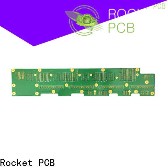

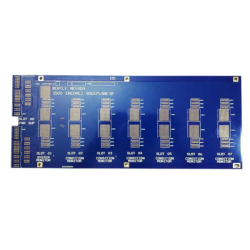

The backplane has a lot of distinctive features.
Size
A large part of the backplane is connected to some of the other boards at right angles. This requires that the backplane be much larger than conventional PCBs and that some backplanes even reach the 762mmx1066.8mm
The number of layers
In terms of the most common backplane, its layer is already in the 16~28, this number is much higher than the ordinary PCB
Thickness
From the structure of the backplane itself, in order to be able to withstand more mechanical stress, it has to be designed much thicker than ordinary PCB. In most cases, the designer has to increase its thickness, and the typical backplane thickness is 2mm-4mm, which can be as thick as 4mm-6mm.
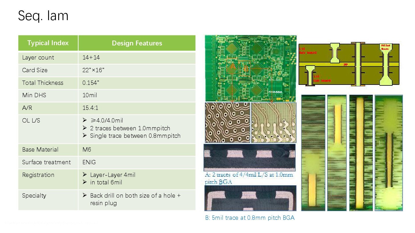
With the continuous development of science and technology, users of bandwidth requirements are becoming more and more stringent, which requires that the design of the backplane to be precise and rigorous enough, the production process of ordinary PCB has been far from meeting the needs of modern production. In order to produce a backplane that meets a variety of conditions, it is necessary to eliminate some of the original conventional equipment and replace it with a hybrid bus structure and assembly technology.

◪ Panel sizes up to 54 inches
◪ Over 70 layers
◪ Blind and back drilled through holes
◪ Dual diameter holes
◪ Heavy copper layers
◪ Connector expertise


Quick Links
About Us
Contact Us
Tel:(+86) 158 9965 5195
Office:(+86) 755 23040566
E-mail:sales@sllpcb.com
Microsoft Teams:hank_168
WhatsApp:+86 186 0723 3179
Office Address:2207,Bid 4,He Gu Shan Hui Cheng,35#,Guang Tian Ro Yanluo street, Song Gang Town,518105 SHENZHEN, CHINA
Plant ADD: No 69, Lianfeng North Road, Xianxi Area, ChangAn Town, Dongguan, China.


