English


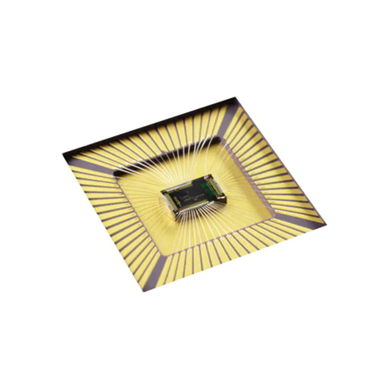

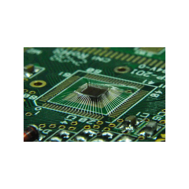
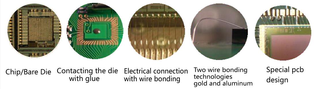
Wire bonding – the excellent connection between the chip and circuit board substrate. This process makes it possible to apply an IC (integrated circuit) to an IC substrate using minimum space.
Wire bonding is a method that uses thin metal wires and uses heat, pressure, and ultrasonic energy to tightly weld the metal wires with the substrate pad to realize the electrical interconnection between chips and substrates and the information exchange between chips. Under ideal control conditions, electron sharing, or atomic diffusion will occur between the wire and the substrate, so that the bonding between the two metals can be realized on the atomic scale.
Although not common, wire bonding can be used to connect IC to other electronic devices or from one printed circuit board (PCB) to another. Wire bonding is generally considered to be the most cost-effective and flexible interconnection technology and is used to assemble most semiconductor packages. If the design is reasonable, wire bonding can be used at frequencies above 100 GHz.
There are some new requirements on the surface of the bonded pad and PCB itself for direct chip connection without the shell on the PCB. The best material for welding pads is pure gold metallization. Surface quality can be measured during wire bonding using an ultrasonic power process window. The results show that the surface and PCB have considerable influence on the ultrasonic and thermoacoustic bonding process.
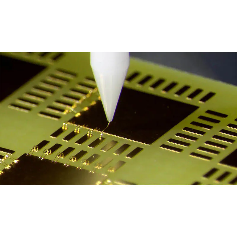
The function of wire bonding is to introduce and export electrical connections from the core components. In industry, three kinds of wire bonding positioning platform technologies are usually adopted: hot pressing wire bonding (TC), wedge-wedge ultrasonic wire bonding (US), and thermal ultrasonic wire bonding (TS).
Pressure and heating are used to make the atoms on the contact surface between the metal wire and the welding area reach the range of atomic gravity and realize bonding. One end is spherical, and the other end is a wedge, which is commonly used for Au wire bonding.
The ultrasonic generator makes the cleaver produce horizontal elastic vibration and applies downward pressure at the same time. Under the action of two kinds of forces, the cleaver drives the wire to quickly rub on the metal surface of the welding area, and the wire is plastically deformed and in close contact with the bonding area to complete the welding. It is commonly used for Al wire bonding. Both ends of the bonding point are wedge-shaped thermal ultrasonic bonding: it is used for the bonding of Au and Cu wires. If ultrasonic energy is adopted, an external heat source shall be provided during bonding.
T/S bonding is the bonding of the bonding wire and the bonded surface under the ultrasonic vibration of the bonding cleaver, the pressure of the cleaver and the high temperature of the bonding surface (typical temperature is 150 ℃).
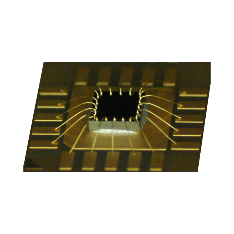
For ball bonding and wedge bonding, the shapes of the two wiring points can be the same or different.
Ball bonding is a non-directional process, that is, the second bonding position can be in any direction of the first bonding. At present, the wire used in ball bonding is almost gold wire, accounting for almost 98% of all wire bonding. The way of ball bonding can be hot pressing bonding or thermoacoustic bonding, which is much faster than wedge bonding.


Wedge bonding is a single direction bonding, that is, the position of the second bonding must be on the axis of the first bonding point and behind the first bonding point. Of course, there is also the bonding of "s" shaped wires. The position of its second bonding point may not be on the axis of the first bonding point, and the direction of the second bonding point is still greatly limited. The wires bonded by wedge welding can be aluminum wires, copper wires, or gold wires. Wedge bonding is much slower than ball bonding, but it has a smaller spacing bonding ability and can bond strip wires. Wedge bonding is usually ultrasonic bonding at room temperature, or hot pressing, or thermoacoustic bonding. The advantages of wedge bonding include narrow pad spacing, low wire arc, controllable wire length, and low-temperature bonding.


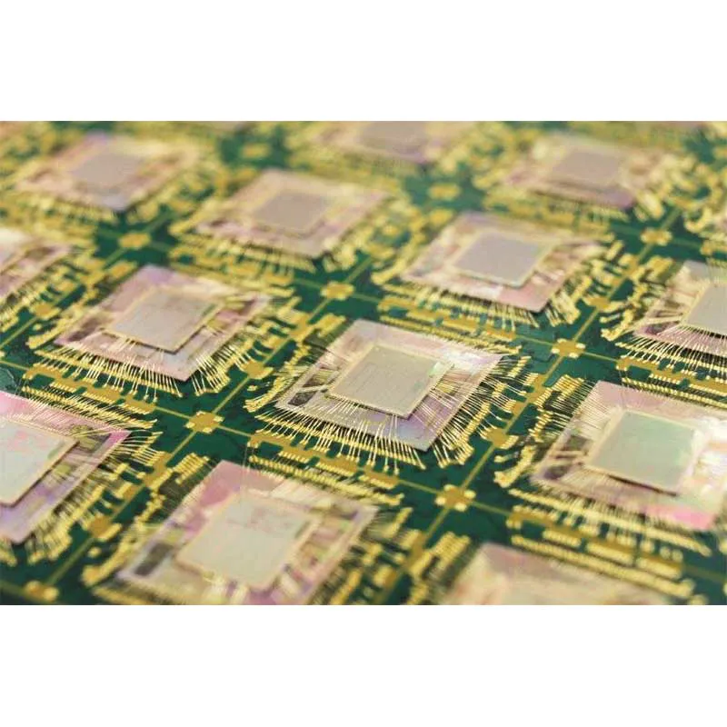
The characteristics of low cost, high reliability, and high output make WB the main process method for chip interconnection, which is used for the following packaging:
Ceramic and plastic BGA, SCP and MCP ceramic and plastic QFP chip size package (CSP).
Gold wire bonding

As a product family, the wire bonding wire is one of the key materials of semiconductor packaging. Its function is to realize the electrical connection between the semiconductor chip and pin and play the role of current import and export between the chip and the outside world. At present, the bonding wire is mainly composed of gold wire, copper wire, aluminum wire, silver wire, and precious/base metal composite wire. Aluminum wire and copper wire are mainly used in medium and low gear circuits, and precious metal wire accounts for more than 80% of the total medium and high products.
1) Good bonding characteristics are related to the following factors,
a. The resistance of the bonding wire solder joint and the space occupied in the chip and wafer
b. Clearance required for welding
c. Conductivity per unit volume
d. The ductility, chemical properties, corrosion resistance, and metallurgical properties of the bonding wire
2) The bonding alloy wire used for bonding shall have the following characteristics:
a. The dimensional accuracy shall be high and uniform without bending
b. The surface is smooth and clean without contamination and scars
c. With specified breaking force and elongation
d. There is no ripple at the weld joint during welding
e. During ball welding, the roundness of the molten ball shall be high
It is widely used in hot pressing and thermoacoustic welding. The wire surface should be smooth and clean to ensure strength and prevent wire blockage. Pure gold has good tensile strength and ductility. High pure gold is too soft. Generally, about 5-10 ppm be or 30-100 ppm Cu is added. The wire strength of be doped is generally 10-20% higher than that of Cu doped.
1. Pure aluminum is too soft to be drawn into wire. Generally, 1% Si or 1% Mg is added to improve the strength.
2. At room temperature, 1% Si exceeds the solubility in aluminum, resulting in Si segregation. The size and quantity of segregation depend on the cooling degree. Too slow cooling leads to more Si particles. Si particle size affects the plasticity of silk thread, and the second phase is the potential location of fatigue cracking.
3. The strength of aluminum wire doped with 1% magnesium is equivalent to that doped with 1% silicon.
4. The fatigue strength is better because the equilibrium solubility of magnesium in aluminum is 2%, so there is no second phase precipitation.
1. Recently, people began to pay attention to the application of copper wire in IC bonding.
2. It is cheap and has sufficient resources.
3. It has a strong ability to resist fluctuation (shaking in the plane in the vertical length direction) in plastic packaging.
4. The main problem is bonding.
5. It is harder than gold and aluminum, resulting in craters and damage to the metal welding area.
6. Due to easy oxidation, it should be bonded in a protective atmosphere.

Table 1 three bonding wire processes
Bonding wire principle | pressure | temperature | Ultrasonic energy | Wire | Pad | Wire diameter |
Hot-press welding | high | No | gold | Aluminum, gold | φ15-100um | |
Ultrasonic welding | low | 25℃ | Yes | Aluminum, gold | Aluminum, gold | φ10-500um |
Thermal ultrasonic welding | low | 100℃-150℃ | Yes | gold | Aluminum, gold | φ15-100um |
In general wire bonding, the cross-section of the used wire is circular, mainly because the wire with a circular cross-section is easy to pull, and the resistance of wire feeding during bonding is small, which is also convenient for wire feeding. However, in the case of high frequency, especially in the assembly of optoelectronic devices, considering the skin effect of high-frequency current (the current is concentrated to the surface of the conductor), in order to improve (or maintain) the conductivity of the bonding wire, it is necessary to increase the perimeter of the cross-section of the bonding wire. Therefore, in such devices, it is considered to use rectangular section wire instead of circular section wire for bonding, but when using strip wire for bonding, the direction of bonding wire cannot be arbitrary. Therefore, generally, ball welding technology is not used for bonding, but wedge welding technology is used for bonding. Therefore, wire strip wedge bonding appears. At present, Due to the increase of optoelectronic device assembly, the application of wire strip wedge bonding will be more and more widely.
1) The cross-section of a stripped wire is rectangular. The standard strip wire size range is 6.3um×10.7y to 50.8μm×508μm. Due to the different process methods adopted by the manufacturer in the process of manufacturing wires and the different amounts of trace elements, the physical properties of various wires are different. Therefore, when using these wires for bonding, different bonding parameters should be selected according to different wires to make the quality of products meet the process requirements.
2) Strip wire wedge welding bonding process is as follows
1. The ribbon wire extends out of the end of the bonding cleaver, and the bonding machine reduces the height of the bonding head to make the cleaver contact with the surface of the first bonding position for the first bonding point operation.
2. After the first bonding is completed, the clamp is opened and moved back one tail wire distance.
3. The bonding head of the bonding machine rises, and the cleaver rises to the arc height position.
4. The bonding machine moves the welding head horizontally so that the cleaver moves above the second bonding position, reduces the height of the welding head so that the cleaver contacts the surface of the second bonding. At this time, the wire clamp is closed and bonded.
5. After the second bonding, the wire clamp moves backward and breaks the wire.
6. Move the clamp forward (moving distance = tail wire length + bonding point length) and send out the section wire from the end of the cleaver (the part protruding from the cleaver is the tail wire for the next bonding, and its length can be adjusted or set).
3) There are two different wire pulling methods for circular wire wedge and strip wire wedge. Wire clamp wire pulling and workbench wire pulling. Bonding machines (manual or automatic bonding machines) can use one of the wires pulling modes, and some bonding machines can switch between the two-wire pulling modes.
In the machine structure of pulling wire with wire clamp, the wire clamp is installed behind the bonding cleaver. After the second bonding problem, the wire clamp moves backward and breaks the wire. This is the most common process and is very reliable because the cleaver still stops at the second bonding point during wire clamping and pulling, making it easy for the clamp to pull the wire. During wire pulling, the wire belt is pulled off at the root of the bonding point because the cross-sectional area of the wire at this position is the smallest (during bonding, the wire belt at the heel of the bonding point is extruded and deformed to reduce the cross-sectional area.
The end surface of the standard clamp is made of sapphire or precision polished metal to avoid damaging the wire surface. For the wire belt, the end surface of the clamp is made of ceramic or slightly rough material to better clamp the wire during wire pulling. This is very important for the wire with a large cross-sectional area.
For the bonding machine with 30 ° wire feeding angle, the bonding wire still remains 30 after passing through the clamp and cleaver hole. At this time, the position of the clamp is the most ideal, and it is not allowed to increase the gap between the clamp and the cleaver to facilitate the bonding of the deep cavity packaging circuit. If this problem is increased, the wire between the clamp and the cleaver will be bent or the cleaver hole will be blocked during wire feeding, and then Wire to the problems of tail wire length consistency, radian height consistency, and wire breakage. Generally speaking, the tail wire length of the bonding point is only about 12.7m. During the process of clamping and sending out the tail wire, any slight blockage may cause improper tail wire length. For the bonding of deep cavity sealing circuit, the bonding machine with 38 °, 45 °, and 60 ° wire feeding structure can be used.
In some packages, the colloid of the package is deep, or there are other parts behind the second bonding, or some other reasons will hinder the wire pulling of the wire clamp. Therefore, the wire clamp cannot be used to break the wire, but the workbench needs to be used to break the wire. The difference between the workbench wire pulling and the wire clamp wire pulling is that the workbench moves while the wire clamp does not move, and the wire clamp is only in the drawing position In the open and closed state, in the bench wire pulling process, when the second bonding is completed, the bonding cleaver rises slightly to leave the bonding surface (at this time, the clamp is open)
The X-Y worktable of the machine moves in the opposite direction to the bonding wire (the X-Y worktable only moves in the Y direction when pulling the wire in the non-rotating bonding head bonding machine), pull out a section of wire (as the tail wire of the first bonding point of the next wire), then the clamp is closed, the worktable continues to move, and the bonding wire is pulled off at the weakest point, that is, the root of the second bonding point.
For high-frequency applications, Strip wire bonding is a better method, even better than circular wire in many aspects, but there are still some problems. In use, the IC packaging structure will decide whether to use a wire clamp or workbench. The wire tape bonding cleaver, wire tape, and bonding parameters need to be tested to find out the best cleaver size and wire Tape specifications and bonding parameters.
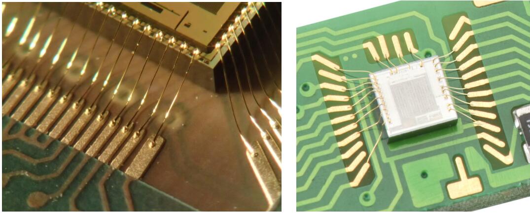
Common PCB plating and wire bonding methods include
◪ Aluminum Wedge Wire Bonding and ENIG Plating
◪ Gold Ball Wire Bonding and soft gold plating
◪ Gold Ball Wire Bonding with ENEPEG plating
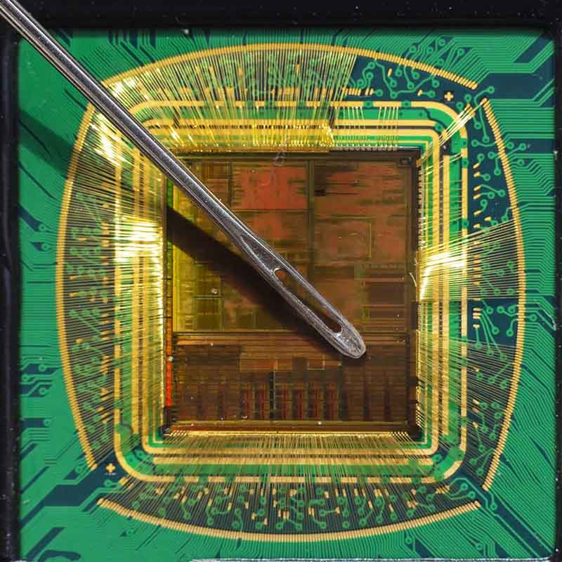
Inner and outer double-level 20um micron gold wire bonding


Rocket PCB has a set of bonding equipment with unique functions. Our wide range of machines provides customers with the flexibility they need for a wide range of bonding applications. Rocket PCB offers a variety of wire bonding technologies. Our wire bonding capabilities include:
Ball Bonding——wire diameters ranging from 0.8 to 2.0 mils (20 microns to 50 microns).
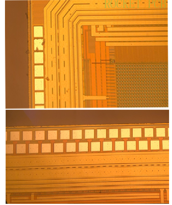
We offer standard, fine pitch, and ultra-fine pitch bonding down to 35 microns.
Multi-tier wire bonding up to 4 rows is available.
Wedge Bonding——Wire diameters range from 1.0 to 2.0 mils (18 microns to 50 microns).
Aluminum wedge bonding is commonly used for Chip-on-Board (COB). By utilizing aluminum wire, the PCB can be manufactured with a plating method of lower cost, and the PCB is usually applied to COB LED.
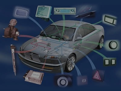
Heavy Wire Bonding—— Wire diameters range from 4.0 to 20.0 mils (102 microns to 508 microns). Heavy Wire is usually applied to power semiconductor devices and the automotive industry.
Stud Bumping——Wire diameters range from 0.7 to 2.0 mils (18 microns to 50 microns). Stud Bumping is usually applied to the gold stud bumping prior to Flip chip attachment. Thermosonic flip Chip and thermocompression flip Chip undergo flip-chip attachment process and are equipped with gold stud bumps. Epoxy attachment is also available.
Strip Wire Bonding——The size of gold ribbons can be customized. Please contact Rocket PCB with your specific requirement.
COB Wire Bonding——Rocket has developed advanced gold or aluminum wire bonding for PCB manufacturing and we can offer advanced COB wire bonding technology.


Product Message
QUICK LINKS
CONTACT US
Office: (+86) 755 23040566
Tel: (+86) 158 9965 5195
E-mail: sales@rocket-pcb.com
Skype: Hans@Rocket-PCB
Whatsapp: 86 1589965 5195
Office Address: 2207,Bid 4,He Gu Shan Hui Cheng,35#,Guang Tian RoYanluo street, Song Gang Town,518105 SHENZHENG, CHINA
Plant ADD.: No 69, Lianfeng North Road, Xianxi Area, ChangAn Town, Dongguan, China.