Latest products
arduino spider robot (quadruped)
by:Rocket PCB
2019-12-02
Hey guys!
Here is a new tutorial to guide you step by step while making this super amazing electronic project, which is the \"crawling robot\" called \"spider robot \".
As everyone noticed the rapid development of robotics, we decided to bring you to a higher level in robotics and robotics.
Not long ago, we started to do some basic electronic projects and basic robots, such as the PICTO92 line follower robot project.
On another level, we have started using this robot, which is a basic robot in the concept, but it becomes a bit complicated if you get to know its program in depth.
As these gadgets are very expensive in the web store, we provide step by step guidance to guide you to make your own spider robots.
This project is very convenient and can be specially made after obtaining the custom PCB we ordered from JLCPCB to improve the appearance of our robot, and there are enough documents and code in this guide to allow you to easily create your crawler.
It took us only 7 days to complete the project, only 2 days to complete the hardware production and assembly, and then 5 days to prepare the code and android app.
Control the robot through it.
Before we start, let\'s take a look at the definition of the name. Our robot is the basic representation of the sipder action, but it will not perform the exact same body action, because we only use four legs instead of eight.
Because it has four legs and uses these legs for action, it is also named a four-legged robot to identify the body position of the robot and also to control the body balance of the robot, the movement of each leg is related to other legs.
Leg robots handle terrain better than wheel robots and move in a variety of animal ways.
However, this makes leg robots more complex, and many manufacturers do not have access to leg robots.
In addition, the manufacturing cost and high depth that the manufacturer should spend to make the whole-body quadrupeds, because it is based on a servo motor or a stepping motor, both of which are more expensive than a DC motor to use for wheeled robots.
You will find that the four-legged animals are very rich in nature, because the four legs can maintain passive stability, or the ability to stand without actively adjusting the position.
The same is true of robots. A four-
The leg robot is cheaper and simpler than the one with more legs, but it can still achieve stability.
The servo motor defined in Wikipedia is a rotary actuator or linear actuator that allows precise control of the angle or linear position, speed, and acceleration. [1]
It is connected by a suitable motor with a sensor for position feedback.
It also requires a relatively complex controller, usually a dedicated module specifically designed for servo motors.
The servo motor is not a specific category of motor, although the term \"servo motor\" is generally used to refer to a motor that is suitable for closure-
Loop control system.
Generally speaking, the control signal is a square wave pulse sequence.
The common frequencies of the control signals are 44Hz, 50Hz and 400Hz, respectively.
What determines the servo position is the positive pulse width.
The positive pulse width is around 0.
5ms will cause the servo Horn to be deflected to the left as much as possible (
Depending on the servo in question, usually around 45 to 90 degrees).
The width of the positive pulse is about 2. 5ms to 3.
0ms will cause the servo to deflate to the right as much as possible.
Pulse width of about 1.
5ms will keep the servo in a neutral position of 0 degrees.
The output high voltage is generally between 2.
5 V and 10 V (Typical 3 v).
Output low voltage range from-40mV to 0V. JLCPCB (
Shenzhen jialichuang Electronic Technology Development Co. , Ltd. , Ltd. )
Is the largest PCB prototype enterprise in China and
Technical manufacturer specializing in the production of fast PCB prototypes and small PCB
Mass production of PCB.
JLCPCB has more than 10 years experience in PCB manufacturing, more than 200,000 customers at home and abroad, more than 8,000 PCB prototype online orders and a small amount of PCB production every day.
Annual production capacity of 200,000 square meters. m.
For various 1-layer, 2-layer or multi-layer PCBs.
JLC is a professional PCB manufacturer with large scale, good equipment, strict management and excellent quality.
In order to produce the PCB, I compared the prices of many PCB manufacturers, and I chose the best PCB supplier and the cheapest PCB supplier for JLCPCB to order this circuit.
All I need to do is simply click and upload the gerber file and set some parameters like PCB thickness color and quantity and then, it only cost me two dollars to get my PCB in five days.
I used Arduino Nano to control the whole system when it showed pictures of the related scheme, and I also designed the robot spider shape to make this project better.
You can get the circuit (PDF)file from here.
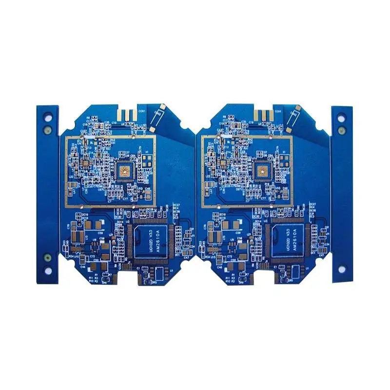
As you can see in the picture above, the PCB is made very well, I have the same PCB Spider shape we designed and all the labels and signs are there to guide me in the welding steps.
If you would like to order the same circuit design, you can also download the Gerber file for this circuit from here.
Now let\'s review the necessary components needed for this project, so as I said, I\'m using the Arduino Nano to run all 12 servo motors for the four legs of the robot.
The project also includes an OLED display for displaying the face of the Cozmo and a Bluetooth module for controlling the robot through the android app.
In order to create this kind of project we need: Now that we have the PCB ready, all the components are welded well, after that we need to assemble the robot body, the process is very simple, just follow the steps I show, we first need to prepare one side for each leg and make an led, we need two servo motors for joints, and the printed part of the hip, femur and Shin with this small connecting part.
About the body parts of the robot, you can download its STL file from here.
Starting with the first servo, put it on the socket, fix it with the screw, after that, rotate the servo axe to 180 ° without placing the connecting screw and moving to the next section, that is, the femur, using the first servo joint axe and accessories.
The last step to complete the leg is to place the second joint, I mean the second servo to hold the third part of the leg, the Coxa piece.
Now repeat the same thing for all legs and get four legs ready.
After that, remove the chassis above, place the rest of the servo system in the socket, and then connect each leg to the appropriate servo system.
Only the last printed part is the robot chassis at the bottom, where we will place the board and discuss android, which allows you to connect to your robot via Bluetooth and make left and right turns moving forward and backward, it also allows you to control the light color of the robot in real time by selecting the desired color from this color wheel.
You can download the android app for free from this link: hereNow we are ready to run the robot, but we need to set the joint angle first, so Upload the installation code and connect the servo system via 90 degrees, you can put each servo in the right position and don\'t forget to connect the 7v DC battery to run the robot.
Next we need to upload the master program using the android app to control the robot.
You can download these two programs from these links :-
Zoom servo code: Download link-
Spider robot main program: Download the link after uploading the code I connected to the OLED display to display the Cozmo robot smile I made in the main code.
As you can see in the picture above, the bot follows all the instructions sent by my smartphone and there are some other improvements that need to be made to make it more buttery.
Here is a new tutorial to guide you step by step while making this super amazing electronic project, which is the \"crawling robot\" called \"spider robot \".
As everyone noticed the rapid development of robotics, we decided to bring you to a higher level in robotics and robotics.
Not long ago, we started to do some basic electronic projects and basic robots, such as the PICTO92 line follower robot project.
On another level, we have started using this robot, which is a basic robot in the concept, but it becomes a bit complicated if you get to know its program in depth.
As these gadgets are very expensive in the web store, we provide step by step guidance to guide you to make your own spider robots.
This project is very convenient and can be specially made after obtaining the custom PCB we ordered from JLCPCB to improve the appearance of our robot, and there are enough documents and code in this guide to allow you to easily create your crawler.
It took us only 7 days to complete the project, only 2 days to complete the hardware production and assembly, and then 5 days to prepare the code and android app.
Control the robot through it.
Before we start, let\'s take a look at the definition of the name. Our robot is the basic representation of the sipder action, but it will not perform the exact same body action, because we only use four legs instead of eight.
Because it has four legs and uses these legs for action, it is also named a four-legged robot to identify the body position of the robot and also to control the body balance of the robot, the movement of each leg is related to other legs.
Leg robots handle terrain better than wheel robots and move in a variety of animal ways.
However, this makes leg robots more complex, and many manufacturers do not have access to leg robots.
In addition, the manufacturing cost and high depth that the manufacturer should spend to make the whole-body quadrupeds, because it is based on a servo motor or a stepping motor, both of which are more expensive than a DC motor to use for wheeled robots.
You will find that the four-legged animals are very rich in nature, because the four legs can maintain passive stability, or the ability to stand without actively adjusting the position.
The same is true of robots. A four-
The leg robot is cheaper and simpler than the one with more legs, but it can still achieve stability.
The servo motor defined in Wikipedia is a rotary actuator or linear actuator that allows precise control of the angle or linear position, speed, and acceleration. [1]
It is connected by a suitable motor with a sensor for position feedback.
It also requires a relatively complex controller, usually a dedicated module specifically designed for servo motors.
The servo motor is not a specific category of motor, although the term \"servo motor\" is generally used to refer to a motor that is suitable for closure-
Loop control system.
Generally speaking, the control signal is a square wave pulse sequence.
The common frequencies of the control signals are 44Hz, 50Hz and 400Hz, respectively.
What determines the servo position is the positive pulse width.
The positive pulse width is around 0.
5ms will cause the servo Horn to be deflected to the left as much as possible (
Depending on the servo in question, usually around 45 to 90 degrees).
The width of the positive pulse is about 2. 5ms to 3.
0ms will cause the servo to deflate to the right as much as possible.
Pulse width of about 1.
5ms will keep the servo in a neutral position of 0 degrees.
The output high voltage is generally between 2.
5 V and 10 V (Typical 3 v).
Output low voltage range from-40mV to 0V. JLCPCB (
Shenzhen jialichuang Electronic Technology Development Co. , Ltd. , Ltd. )
Is the largest PCB prototype enterprise in China and
Technical manufacturer specializing in the production of fast PCB prototypes and small PCB
Mass production of PCB.
JLCPCB has more than 10 years experience in PCB manufacturing, more than 200,000 customers at home and abroad, more than 8,000 PCB prototype online orders and a small amount of PCB production every day.
Annual production capacity of 200,000 square meters. m.
For various 1-layer, 2-layer or multi-layer PCBs.
JLC is a professional PCB manufacturer with large scale, good equipment, strict management and excellent quality.
In order to produce the PCB, I compared the prices of many PCB manufacturers, and I chose the best PCB supplier and the cheapest PCB supplier for JLCPCB to order this circuit.
All I need to do is simply click and upload the gerber file and set some parameters like PCB thickness color and quantity and then, it only cost me two dollars to get my PCB in five days.
I used Arduino Nano to control the whole system when it showed pictures of the related scheme, and I also designed the robot spider shape to make this project better.
You can get the circuit (PDF)file from here.
As you can see in the picture above, the PCB is made very well, I have the same PCB Spider shape we designed and all the labels and signs are there to guide me in the welding steps.
If you would like to order the same circuit design, you can also download the Gerber file for this circuit from here.
Now let\'s review the necessary components needed for this project, so as I said, I\'m using the Arduino Nano to run all 12 servo motors for the four legs of the robot.
The project also includes an OLED display for displaying the face of the Cozmo and a Bluetooth module for controlling the robot through the android app.
In order to create this kind of project we need: Now that we have the PCB ready, all the components are welded well, after that we need to assemble the robot body, the process is very simple, just follow the steps I show, we first need to prepare one side for each leg and make an led, we need two servo motors for joints, and the printed part of the hip, femur and Shin with this small connecting part.
About the body parts of the robot, you can download its STL file from here.
Starting with the first servo, put it on the socket, fix it with the screw, after that, rotate the servo axe to 180 ° without placing the connecting screw and moving to the next section, that is, the femur, using the first servo joint axe and accessories.
The last step to complete the leg is to place the second joint, I mean the second servo to hold the third part of the leg, the Coxa piece.
Now repeat the same thing for all legs and get four legs ready.
After that, remove the chassis above, place the rest of the servo system in the socket, and then connect each leg to the appropriate servo system.
Only the last printed part is the robot chassis at the bottom, where we will place the board and discuss android, which allows you to connect to your robot via Bluetooth and make left and right turns moving forward and backward, it also allows you to control the light color of the robot in real time by selecting the desired color from this color wheel.
You can download the android app for free from this link: hereNow we are ready to run the robot, but we need to set the joint angle first, so Upload the installation code and connect the servo system via 90 degrees, you can put each servo in the right position and don\'t forget to connect the 7v DC battery to run the robot.
Next we need to upload the master program using the android app to control the robot.
You can download these two programs from these links :-
Zoom servo code: Download link-
Spider robot main program: Download the link after uploading the code I connected to the OLED display to display the Cozmo robot smile I made in the main code.
As you can see in the picture above, the bot follows all the instructions sent by my smartphone and there are some other improvements that need to be made to make it more buttery.
Custom message